Introduction: Sourcing Vfd Variable Frequency Drive for Industrial Use
In an era where industrial energy efficiency and precision motor control define operational competitiveness, the Variable Frequency Drive (VFD) has evolved from a simple speed controller to the central nervous system of modern automation. Whether optimizing HVAC systems in commercial complexes, controlling conveyors in heavy industry, or driving submersible pumps in off-grid agricultural solar installations, VFDs deliver measurable ROI through reduced mechanical stress, soft-start capabilities, and demand-responsive energy consumption that directly impacts utility costs.
Yet for procurement teams, EPC contractors, and system integrators navigating global supply chains, sourcing the optimal drive presents a multifaceted engineering challenge. The market spans diverse power electronic topologies—from standard six-pulse diode converters to active front-end regenerative systems and specialized solar pump inverters with integrated MPPT algorithms. Each application demands rigorous evaluation of harmonic distortion limits, ingress protection ratings for harsh environments, and compatibility with permanent magnet versus induction motor technologies.
This comprehensive guide demystifies the industrial VFD procurement process for technical decision-makers. We examine critical specification parameters including voltage class selection, switching frequency impacts on motor insulation life, and thermal derating factors in high-altitude deployments. You’ll discover how to evaluate manufacturer capabilities beyond catalog ratings—assessing firmware customization options, global service networks, and compliance with IEC 61800 and UL 61800 standards. From sizing drives for quadratic torque pump loads to specifying integrated PLC functionality for Industry 4.0 integration, we provide the technical framework necessary to specify drives that minimize total cost of ownership while ensuring reliability across your automation infrastructure.
Article Navigation
- Top 2 Vfd Variable Frequency Drive Manufacturers & Suppliers List
- Introduction: Sourcing Vfd Variable Frequency Drive for Industrial Use
- Technical Types and Variations of Vfd Variable Frequency Drive
- Key Industrial Applications for Vfd Variable Frequency Drive
- Top 3 Engineering Pain Points for Vfd Variable Frequency Drive
- Component and Hardware Analysis for Vfd Variable Frequency Drive
- Manufacturing Standards and Testing QC for Vfd Variable Frequency Drive
- Step-by-Step Engineering Sizing Checklist for Vfd Variable Frequency Drive
- Wholesale Cost and Energy ROI Analysis for Vfd Variable Frequency Drive
- Alternatives Comparison: Is Vfd Variable Frequency Drive the Best Choice?
- Core Technical Specifications and Control Terms for Vfd Variable Frequency Drive
- Future Trends in the Vfd Variable Frequency Drive Sector
- B2B Engineering FAQs About Vfd Variable Frequency Drive
- Disclaimer
- Conclusion: Partnering with Boray Inverter for Vfd Variable Frequency Drive
Technical Types and Variations of Vfd Variable Frequency Drive
Variable Frequency Drives vary significantly in their internal topologies, control algorithms, and input power configurations. For industrial engineers and EPC contractors specifying equipment for agricultural automation or industrial motor control, selecting the appropriate drive architecture is critical for optimizing energy efficiency, ensuring grid compatibility, and meeting specific torque demands across operational speed ranges. Below are the four primary technical classifications relevant to modern automation and solar pumping applications.
| Type | Technical Features | Best for (Industry) | Pros & Cons |
|---|---|---|---|
| General Purpose V/Hz VFDs | • 6-pulse diode rectifier topology • Constant Volts-per-Hertz (V/Hz) ratio control • PWM output with adjustable carrier frequency (2–16 kHz) • Standard DC bus with electrolytic capacitor bank |
Centrifugal pumps, HVAC systems, Fans, General industrial machinery | Pros: Cost-effective commissioning, high reliability for variable torque loads, minimal parameter setup required Cons: Limited starting torque at low speeds (<150% at 3Hz), poor dynamic response to load changes, potential motor heating during prolonged low-speed operation |
| Vector Control (FOC) VFDs | • Field Oriented Control (FOC) algorithm with motor modeling • Auto-tuning for stator resistance and inductance • 150–200 |
Key Industrial Applications for Vfd Variable Frequency Drive
Variable frequency drives have evolved from simple motor speed controllers to sophisticated automation nodes that optimize energy consumption across diverse industrial ecosystems. For EPC contractors and system integrators, selecting the appropriate VFD topology—whether for solar-powered agricultural installations or heavy-duty mining conveyors—requires understanding sector-specific load profiles, environmental constraints, and integration protocols. The following applications represent high-impact deployment scenarios where VFD technology delivers measurable ROI through energy optimization, process control enhancement, and grid independence.
| Sector | Application | Energy Saving Value | Sourcing Considerations |
|---|---|---|---|
| Agriculture & Solar Irrigation | Solar pump inverters for borehole/submersible pumps, surface irrigation, and drip systems; AC/DC hybrid pumping stations | 40–60% reduction in irrigation energy costs; elimination of diesel generator dependency; MPPT efficiency >99% minimizing PV array waste | IP66/NEMA 4X enclosures for UV/weather exposure; wide DC input voltage range (400V–800V) for solar array compatibility; anti-islanding protection (UL 1741/IEC 62116); GPRS/4G remote monitoring for dispersed farm networks |
| Water & Wastewater Treatment | Centrifugal pumps, aeration blowers, filter backwash systems, and lift station pumps | 20–40% energy savings via affinity laws (energy ∝ speed³); reduced water hammer and mechanical wear extending pump life by 30% | PID control algorithms for constant pressure/flow; active harmonic filters (THDi <5%) to protect sensitive PLCs; conformal coating for corrosive atmospheres; redundant cooling and pump staging (cascading) capabilities |
| HVAC & Building Infrastructure | Chilled water pumps, cooling tower fans, air handling units (AHUs), and compressor control | 30–50% fan/pump energy reduction; optimized part-load efficiency; demand-based ventilation reducing peak demand charges | BACnet/Modbus RTU integration for BMS connectivity; low-noise PWM switching algorithms; fire safety override inputs (smoke purge mode); active front end (AFE) drives for regenerative energy and harmonic mitigation |
| Mining & Cement Processing | Conveyor belts, crushers, ball mills, kiln drives, and primary/secondary ventilation fans | 15–30% energy recovery via regenerative braking; soft-start capability reducing mechanical stress and belt maintenance by 25%; process throughput optimization | Heavy-duty overload capacity (150% for 60s); regenerative drive units (IGBT-based); vibration resistance (IEC 60068-2-6, 3M3/3M4); STO (Safe Torque Off) safety functions; conformal coating for cement dust environments |
| Manufacturing & Industrial Automation | Machine tools, extruders, mixers, assembly line conveyors, and rotary screw compressors | 15–25% energy savings; near-unity power factor correction (>0.95); reduced material waste via precise torque/speed control | Sensorless vector or closed-loop vector control for high starting torque; industrial Ethernet protocols (Profinet, EtherNet/IP, Modbus TCP); EMC filters (C2/C3 categories); STO/SS1 safety categories per IEC 61800-5-2 |
Agricultural Irrigation & Solar Pumping Systems
In remote agricultural deployments, solar pump inverters serve as the critical interface between photovoltaic arrays and AC induction motors. Unlike conventional grid-tied VFDs, solar-specific drives must manage highly variable DC input voltages while maintaining Maximum Power Point Tracking (MPPT) to extract optimal energy from PV panels. Engineers should specify drives with dry-run protection (automatic shutdown when water levels deplete) and water level sensor integration to prevent pump cavitation. For large-scale irrigation projects, VFDs with automatic voltage boosting compensate for morning/afternoon low-irradiance conditions, ensuring consistent flow rates without battery storage. The integration of IoT-enabled remote monitoring allows agricultural project managers to track flow rates, energy yield, and system faults across dispersed installations via centralized SCADA platforms.
Water Treatment & Distribution Infrastructure
Municipal water systems present unique challenges due to the affinity laws governing centrifugal pumps—reducing pump speed by 20% yields approximately 50% energy savings. Modern VFDs in this sector employ sophisticated PID control loops that maintain constant discharge pressure regardless of fluctuating demand, eliminating energy-wasting throttling valves. For wastewater aeration blowers, dissolved oxygen (DO) sensor integration with VFDs enables precise biological process control while reducing blower energy by up to 40%. Sourcing considerations must prioritize harmonic mitigation, as the high switching frequencies of standard VFDs can disrupt sensitive instrumentation and PLC networks in treatment plants. Specifying drives with active front ends or DC link chokes ensures compliance with IEEE 519 / IEC 61000-3-6 harmonic standards.
HVAC & Commercial Building Automation
HVAC applications predominantly involve variable torque loads (centrifugal fans and pumps) where VFDs optimize energy during part-load conditions—common in commercial buildings operating below peak design capacity 90% of the time. Critical sourcing factors include BACnet compatibility for seamless Building Management System (BMS) integration, allowing centralized scheduling and demand response participation. Fire safety integration is paramount; VFDs must accept hardwired fire safety override signals to bypass normal control and force fans to full speed for smoke evacuation. Additionally, drives with automatic energy optimization (AEO) algorithms adjust motor voltage based on actual load torque, delivering additional 5–10% savings beyond standard V/Hz control methods.
Mining, Cement & Heavy Industry
In mining and cement processing, VFDs must withstand extreme environmental stress while managing high-inertia loads. Conveyor belt applications benefit from soft-start ramp profiles (S-curves) that eliminate mechanical shock and belt slippage, extending mechanical component life by 20–30%. For downhill conveyors or high-inertia applications like ball mills, regenerative VFDs (active front end or common DC bus with braking units) return deceleration energy to the grid or distribute it to other drives, significantly reducing cooling requirements. Safety functions such as Safe Torque Off (STO) are mandatory for maintenance lockout procedures, immediately removing rotational energy from the motor shaft without removing power from the drive electronics. EPC contractors should verify drives carry appropriate certifications for vibration resistance (3M3/3M4 per IEC 60721-3-3) and conformal coating protection against conductive dust.
Manufacturing & Process Automation
Precision manufacturing requires VFDs with vector control capabilities—either sensorless vector for standard dynamic response or closed-loop vector with encoder feedback for position-critical applications. Extruder and mixer applications demand high starting torque (often 150–200% rated torque) at low speeds, necessitating drives with heavy-duty overload ratings and advanced motor thermal modeling. Network integration via industrial Ethernet (Profinet, EtherNet/IP) enables real-time data exchange with PLCs for predictive maintenance algorithms monitoring bearing wear or process deviations. Electromagnetic compatibility (EMC) is critical in automated facilities; specify drives with integrated EMC filters meeting Category C2 (industrial) or C3 (domestic/light industrial) standards to prevent interference with adjacent control systems.
Top 3 Engineering Pain Points for Vfd Variable Frequency Drive
Scenario 1
The Problem: In industrial facilities with high VFD penetration, the standard six-pulse diode bridge rectifier topology generates characteristic current harmonics (5th, 7th, 11th, 13th) that distort the grid voltage waveform. When combined with power factor correction capacitors, these harmonics create resonance conditions causing transformer overheating, nuisance tripping of protective devices, and non-compliance with IEEE 519 or IEC 61000-3-6 standards. The DC bus ripple inherent in these designs further induces torque pulsations in mechanical loads, accelerating wear in coupled equipment.
The Solution: Specify drives with integrated DC link chokes or active front end (AFE) regenerative technology to reduce total harmonic current distortion (THDi) below 5%. For existing installations, implement line reactors or active harmonic filters at the drive input. Boray VFDs incorporate optimized DC bus capacitance and PWM rectifier options that maintain power quality even in weak grid conditions, protecting upstream infrastructure while ensuring compliance with international harmonic standards.
Scenario 2
The Problem: Modern IGBT-based VFDs utilizing fast-switching algorithms (dv/dt >5,000 V/μs) generate high-frequency common-mode voltage and reflected wave phenomena, particularly in cable runs exceeding 50 meters. This creates shaft voltage buildup in motors, leading to capacitive discharge currents through bearings that cause fluting, pitting, and premature bearing failure (typically within 6–12 months of operation). Additionally, voltage overshoots at the motor terminals stress winding insulation beyond their 1,600V peak rating, risking catastrophic motor failure in inverter-duty applications.
The Solution: Deploy inverter-duty motors with Class H insulation and install output dv/dt filters or sinewave filters to attenuate voltage spikes. For critical applications, specify motors with insulated bearings or install shaft grounding rings to divert bearing currents. Boray VFDs feature adjustable carrier frequency algorithms and soft-PWM switching patterns that minimize common-mode voltage generation, while optional output reactors protect motor insulation integrity in long-cable installations up to 100 meters.
Scenario 3
The Problem: Solar pumping and remote agricultural installations expose VFDs to severe environmental stressors including dust ingress (requiring IP6X protection), humidity, salinity, and extreme temperature fluctuations (-20°C to +60°C). Standard IP20 cabinet-mounted drives suffer from PCB corrosion, electrolytic capacitor evaporation, and cooling fan blockage under these conditions. Additionally, erratic DC input voltage from PV arrays—caused by cloud transients and irradiance fluctuations—triggers DC bus undervoltage faults and destabilizes MPPT tracking, resulting in system downtime where maintenance access is costly and difficult.
The Solution: Specify fully enclosed IP65/66-rated drives with conformal-coated PCBs and passive cooling (heatsink external to electronics compartment) or high-grade ball-bearing fans with replaceable dust filters. Ensure wide DC voltage input ranges (200V–800V) and robust MPPT algorithms that maintain stable output despite rapid irradiance changes. Boray’s solar pump inverters integrate 99% efficiency MPPT controllers with IP65 protection and thermal management designed for harsh environments, eliminating the need for external climate control while maintaining continuous operation across extreme temperature ranges.
Component and Hardware Analysis for Vfd Variable Frequency Drive
The reliability and efficiency of a Variable Frequency Drive (VFD) are fundamentally determined by the quality of its internal electronic architecture. For industrial engineers and EPC contractors specifying drives for demanding applications—particularly solar pumping systems exposed to harsh environmental conditions—understanding the hardware topology is essential for lifecycle cost analysis and system integration. A VFD’s internal structure comprises three primary stages: the rectifier/converter, the DC bus circuit, and the inverter section, each populated by specialized components that dictate performance, thermal efficiency, and Mean Time Between Failures (MTBF).
Power Semiconductor Stage (IGBTs and Rectifier Bridges)
The inverter section relies on Insulated Gate Bipolar Transistors (IGBTs) or Intelligent Power Modules (IPMs) to switch DC bus voltage into variable-frequency AC. In solar pump inverters, these semiconductors must handle wide DC voltage fluctuations (typically 200VDC to 800VDC for single-phase/three-phase systems) while maintaining high switching frequencies (4–16 kHz) for precise motor control. High-quality IGBTs feature junction temperature ratings of 175°C (Tj) versus standard 150°C ratings, providing critical thermal headroom for outdoor installations where ambient temperatures exceed 40°C. The rectifier bridge, typically a six-pulse diode configuration in standard VFDs, must withstand inrush currents during PV array startup and exhibit low forward voltage drop (Vf) to minimize conduction losses.
Control Architecture (DSP/MCU)
The digital signal processor (DSP) or microcontroller unit (MCU) serves as the VFD’s command center, executing Pulse Width Modulation (PWM) algorithms, Maximum Power Point Tracking (MPPT) for solar applications, and real-time protection logic. Industrial-grade controllers operate across extended temperature ranges (-40°C to +85°C) and feature hardware-based protection circuits (hardware trip vs. software trip) for fault conditions like overcurrent or ground faults. For solar pumping, the controller must process analog-to-digital conversions rapidly (≥12-bit resolution) to maintain stable MPPT tracking during irradiance fluctuations, preventing pump cavitation and water hammer.
Thermal Management Systems
Thermal design is the primary determinant of VFD longevity, particularly in agricultural solar installations where drives operate in NEMA 3R or IP65 enclosures with limited airflow. High-performance heatsinks utilize extruded 6063-T5 aluminum with thermal resistance (Rth) below 0.5 K/W and feature anodized surfaces (≥20μm thickness) to prevent oxidation. Forced-air cooling systems employ ball-bearing fans rated for L10 lifetimes exceeding 50,000 hours at 40°C, significantly outperforming sleeve-bearing alternatives in dusty environments. Advanced designs integrate thermal interface materials (TIMs) with phase-change properties to minimize contact resistance between IGBT modules and heatsinks.
DC Bus Energy Storage
The DC link capacitors filter rectified voltage and supply ripple current to the inverter. Electrolytic capacitors, while cost-effective, represent the primary failure mode in VFDs due to electrolyte evaporation at elevated temperatures. Premium drives utilize film capacitors or hybrid electrolytic technologies rated for 100,000+ hours at rated temperature (105°C), with ripple current capacities exceeding 20 Arms. For solar applications, capacitors must withstand continuous voltage stress from open-circuit PV array voltages while maintaining capacitance tolerance within ±5% over the operating life.
Protection and EMI Mitigation Components
Input AC reactors and DC chokes limit inrush current and reduce harmonic distortion, while output dV/dt filters protect motor insulation from reflected wave phenomena—critical for deep-well submersible pumps with long cable runs. Metal oxide varistors (MOVs) and transient voltage suppression (TVS) diodes provide surge protection against lightning-induced transients common in remote solar installations. EMI filters must comply with IEC 61800-3 Category C2/C3 standards to prevent interference with remote monitoring systems.
Component Quality Matrix
| Component | Function | Quality Indicator | Impact on Lifespan |
|---|---|---|---|
| IGBT Module | Converts DC to variable frequency AC; handles motor switching loads | Junction temperature rating (Tj ≤ 175°C), short-circuit withstand time (≥10μs), switching frequency capability (up to 16kHz) | Critical – Thermal cycling causes solder fatigue; 175°C rated modules last 2–3× longer than 150°C units in solar applications |
| DSP Controller | Executes PWM algorithms, MPPT control, fault diagnostics, and communication protocols | Processing speed (≥40 MIPS), industrial temp range (-40°C to +85°C), EMI immunity (IEC 61000-4-4/5) | Critical – Controller failures cause complete drive failure; extended-temp ICs prevent timing drift and latch-up |
| DC Link Capacitors | Filters rectified DC voltage; stores energy for inverter switching; absorbs ripple current | Lifetime rating (L10 life @ 105°C), ripple current capacity (Arms), film vs. electrolytic construction | Very High – Primary wear component; film capacitors offer 100,000+ hour lifespan vs. 20,000 hours for standard electrolytics |
| Cooling Heatsink | Dissipates thermal losses from IGBTs; maintains junction temperatures within safe operating area | Thermal resistance (Rth < 0.5 K/W), material purity (6063-T5 aluminum), anodization thickness (≥20μm) | High – Inadequate cooling reduces semiconductor life by 50% per 10°C rise; essential for 50°C ambient solar sites |
| Cooling Fan | Forced convection for heatsink; required in high-power density designs (>22kW) | Bearing type (ball bearing vs. sleeve), MTBF (L10 ≥ 50,000 hours), IP rating (IP54 minimum for outdoor/agricultural) | Moderate-High – Primary moving part; ball bearings last 3× longer than sleeve bearings in dusty agricultural environments |
| Input/Output Reactors | Limits dV/dt stress on motor windings; reduces reflected wave phenomena; filters line harmonics | Inductance tolerance (±5%), thermal class (H-class insulation, 180°C), current saturation characteristics | Moderate – Prevents insulation degradation in submersible pump motors; extends motor life and reduces system downtime |
| EMI Filter | Suppresses conducted emissions to meet IEC 61800-3; protects against grid transients | Insertion loss (≥60dB @ 150kHz–30MHz), leakage current specifications (<3.5mA), X2/Y2 capacitor ratings | Low-Moderate – Prevents nuisance tripping and ensures regulatory compliance; critical for grid-tied solar pump systems |
| PCB and Interconnects | Mechanical support and electrical connection; carries high currents | Copper weight (≥2oz for power paths), conformal coating (acrylic/urethane), connector plating (gold flash ≥0.1μm) | Moderate – Prevents corrosion in humid climates; heavy copper (3oz) reduces resistive heating and voltage drop |
Procurement Considerations for Solar Pumping
When specifying VFDs for photovoltaic water pumping, EPC contractors should prioritize components rated for wide DC voltage operation (typically 250V–800VDC) to accommodate varying solar irradiance. The combination of high-grade IGBTs (175°C) and film capacitors effectively doubles system MTBF compared to standard industrial drives, reducing Levelized Cost of Energy (LCOE) for agricultural projects. Additionally, verify that cooling systems are rated for the specific particulate conditions—IP54 minimum for outdoor agricultural environments, with optional conformal coating on all PCBs to protect against humidity and corrosive gases common in livestock operations.
Manufacturing Standards and Testing QC for Vfd Variable Frequency Drive
At Boray Inverter, manufacturing excellence for Variable Frequency Drives extends beyond assembly—it encompasses a rigorous validation ecosystem designed to ensure survivability in harsh agricultural environments, solar farm installations, and continuous-duty industrial applications. Our quality control framework addresses the unique stressors of VFD operation: thermal cycling, humidity ingress, electromagnetic interference, and the high-voltage DC bus characteristics inherent to solar pumping systems.
Component-Level Quality Assurance and Traceability
The foundation of VFD reliability begins with semiconductor and passive component selection. We utilize automotive-grade IGBT modules and film capacitors rated for 100,000+ hours of operation under full load conditions. Each PCB assembly undergoes Automated Optical Inspection (AOI) and In-Circuit Testing (ICT) to verify solder joint integrity and component placement accuracy before proceeding to functional testing.
For solar pump inverter applications specifically, DC-link capacitors undergo accelerated life testing (ALT) at 1.5x rated voltage and 105°C ambient to simulate decade-long solar irradiance exposure. Component traceability is maintained through barcode serialization, enabling root-cause analysis should field performance deviations occur.
Environmental Protection and Conformal Coating Standards
Given that agricultural and outdoor solar installations expose VFDs to corrosive atmospheres, humidity, and dust, our manufacturing process incorporates three-layer conformal coating protocols on all control and power PCBs. We utilize polyurethane-based coatings applied via selective robotic spraying to achieve 25-75 micron thickness per IPC-A-610 Class 3 standards, ensuring complete coverage of solder joints and component leads while avoiding heat sink mounting surfaces and connector contacts.
Power terminals and bus bars receive nickel-plating followed by tin-silver alloy finishing to prevent galvanic corrosion in high-humidity climates. Enclosure sealing utilizes dual-durometer EPDM gaskets achieving IP65/IP66 ratings, validated through pressurized dust ingress testing per IEC 60529.
High-Temperature Aging and Burn-In Protocols
Rather than relying on statistical sampling, Boray implements 100% high-temperature aging (HTA) for every VFD unit produced. Following initial assembly, drives undergo a 4-hour burn-in cycle at 50°C ambient temperature with 110% rated load applied to the inverter section. This process serves multiple critical functions:
- Infant mortality screening: Identifies early-fail components (primarily electrolytic capacitors and IGBT gate drivers) before shipment
- Thermal stress relief: Stabilizes solder joints and PCB laminates through controlled thermal cycling between 25°C and 75°C
- Parameter drift detection: Verifies that current sensors, DC bus voltage monitors, and thermal sensors remain within ±1% calibration tolerance under thermal stress
For solar pump VFDs, we additionally conduct UV exposure testing on external keypad membranes and enclosure plastics to validate resistance to solar degradation (ISO 4892-2).
100% Full-Load Dynamic Testing
Unlike manufacturers who perform only no-load or light-load verification, our production line includes regenerative dynamometer test stations capable of absorbing full motor shaft power. Each VFD undergoes:
- Full-load heat run: 2-hour operation at 100% rated current with thermal imaging verification that IGBT junction temperatures remain below Tj(max) under worst-case ambient conditions
- Overload capacity verification: 150% rated current for 60 seconds (simulating pump startup inrush) to confirm IGBT transient thermal management
- Efficiency mapping: Verification of >97% efficiency at rated load and <3% current THD to ensure compliance with IEEE 519 power quality standards
- MPPT algorithm validation (Solar models): Confirmation of 99% tracking efficiency with simulated PV array I-V curves from 200Vdc to 800Vdc input ranges
EMC and Electrical Safety Compliance
All VFDs are manufactured to comply with IEC 61800-3 (adjustable speed electrical power drive systems) for EMC immunity and emissions, and IEC 61800-5-1 for safety requirements. Our testing protocols include:
- Surge immunity: 4kV line-to-earth and 2kV line-to-line per IEC 61000-4-5
- Harmonic current emissions: Verification of compliance with IEC 61000-3-12 for drives >16A input current
- Functional safety: STO (Safe Torque Off) circuits tested for SIL 2 / PLd compliance per IEC 61800-5-2
CE marking is supported by comprehensive technical construction files including risk assessments, material declarations (RoHS 3 compliance), and LVD (Low Voltage Directive 2014/35/EU) conformity.
ISO 9001:2015 Quality Management Integration
Our manufacturing execution system (MES) integrates ISO 9001:2015 protocols with statistical process control (SPC) monitoring of critical parameters: torque precision on terminal screws, conformal coating viscosity, and reflow oven temperature profiles. First Article Inspection (FAI) is conducted for every production batch, with Cpk (process capability index) maintained above 1.67 for all critical-to-quality characteristics.
For EPC contractors and agricultural project managers, this translates to documented reliability: MTBF (Mean Time Between Failures) ratings exceeding 50,000 hours at 40°C ambient, backed by comprehensive factory acceptance test (FAT) reports that include vibration analysis (IEC 60068-2-6) and insulation resistance verification (>100MΩ at 1000VDC).
By implementing these manufacturing standards and exhaustive QC protocols, Boray ensures that every VFD—whether destined for a solar irrigation project in sub-Saharan Africa or a continuous-process manufacturing line—delivers consistent motor control performance with minimal unplanned downtime.
Step-by-Step Engineering Sizing Checklist for Vfd Variable Frequency Drive
Proper sizing of a Variable Frequency Drive (VFD) is the cornerstone of system reliability, energy efficiency, and operational longevity. An undersized drive risks thermal failure and nuisance tripping, while an oversized unit compromises power factor and increases capital expenditure without performance benefits. The following engineering checklist provides a systematic methodology for specifying VFDs in both grid-tied industrial applications and off-grid solar pumping systems.
1. Motor Nameplate Data Extraction & Load Characterization
Begin by documenting all parameters from the motor nameplate and mechanical load requirements:
- Rated Power (HP/kW): Record continuous duty rating. For solar pumping, verify if the hydraulic load requires the motor’s full rated torque or if a smaller motor suffices with VFD speed optimization.
- Voltage & Frequency: Confirm nominal V/Hz ratio (e.g., 460V/60Hz or 380V/50Hz). Verify the VFD’s output voltage range accommodates motor voltage with ±10% tolerance.
- Full Load Amps (FLA): This is your primary sizing metric, not horsepower. Compare against the VFD’s continuous output current rating at 40°C ambient.
- Service Factor (SF): If SF is 1.15, size the VFD for 115% of FLA to maintain thermal headroom. Never size based on SF alone without verifying the actual load profile.
- Torque Profile Classification:
- Variable Torque (VT): Centrifugal pumps and fans (torque ∝ speed²). Standard VFDs suffice.
- Constant Torque (CT): Conveyors, positive displacement pumps. Requires heavy-duty rating or one size larger VFD.
- High Starting Torque: Applications requiring >150% starting torque need vector control or sensorless vector VFDs with appropriate current reserves.
2. Current Rating & Thermal Capacity Verification
Calculate the required drive current capacity using the following methodology:
- Continuous Current: VFD rated current ≥ 1.0 × Motor FLA (minimum). For CT loads, use ≥ 1.1 × FLA.
- Overload Capacity: Verify the drive’s overload rating (typically 150% for 60 seconds or 200% for 3 seconds). Ensure this exceeds the motor’s locked rotor amps (LRA) divided by the drive’s current limit ratio.
- I²t Thermal Integration: For cyclic loads (S2-S9 duty cycles), calculate the RMS current over the complete cycle. The VFD’s thermal model must accommodate the RMS value, not just peak demands.
- Carrier Frequency Derating: If operating above 4kHz switching frequency to reduce motor noise, apply manufacturer derating curves (typically 5-10% current reduction per 2kHz increase).
3. Input Supply Analysis & Voltage Compatibility
Evaluate the upstream power quality and compatibility:
- Voltage Window: For grid-tied systems, verify the VFD’s input voltage range (typically -15% to +10% of nominal). In regions with unstable grids, consider drives with active front ends (AFE) or DC bus chokes.
- Phase Configuration: Three-phase input is standard. For single-phase to three-phase conversion (common in agricultural solar pumping), verify the VFD supports single-phase input derating (typically 50% power reduction) or use a DC-fed solar VFD topology.
- DC Bus Voltage Requirements: For solar pump inverters (like Boray’s solar pump drive series), ensure the Maximum Power Point (MPP) voltage window aligns with the VFD’s DC input range. Typical requirements:
- Minimum DC Voltage: VFD must maintain operation at Vmp_min (typically 250-350VDC for 220VAC motors, 450-550VDC for 380-460VAC motors).
- Maximum DC Voltage: Voc_max must not exceed VFD’s maximum DC bus rating (typically 800VDC for standard drives, 1000VDC for solar-specific units).
4. Solar Array String Calculations (For PV Pumping Applications)
When sizing the photovoltaic array for solar pump VFDs:
- Voltage Window Matching:
- Calculate Voc_max = Panel Voc × Number of panels in series × Temperature Coefficient (typically -0.3%/°C) × Lowest expected temperature (usually -10°C to -25°C).
- Calculate Vmp_min = Panel Vmp × Number of panels in series × Temperature Coefficient × Highest expected temperature (usually 60-70°C cell temperature).
-
Ensure VFD’s MPPT range falls between Vmp_min and Voc_max with 10% safety margin on both ends.
-
Current Sizing:
- Array Isc must exceed VFD input current requirements by 25% minimum.
-
Account for irradiance derating: Size for 70-80% of STC (Standard Test Conditions) wattage to ensure operation during hazy conditions or morning/afternoon sun angles.
-
Power Sizing:
- For centrifugal pumps: PV Array Wattage ≈ 1.3-1.5 × Motor kW (accounts for inverter efficiency ~95%, motor efficiency ~90%, and pump affinity laws).
- For positive displacement pumps: PV Array Wattage ≈ 1.6-1.8 × Motor kW (constant torque load requires higher current reserves).
5. Environmental Derating Factors
Adjust specifications for installation conditions:
- Temperature Derating: If ambient exceeds 40°C (104°F), apply derating curves:
- 1% current reduction per °C above 40°C, or
- 2% current reduction per °C above 50°C (check specific manufacturer curves).
- Consider external cooling or NEMA 3R/4X enclosures for outdoor solar installations.
- Altitude Derating: Above 1000m (3300ft), reduce VFD current capacity by 1% per 100m due to reduced air density and cooling efficiency. Above 2000m, consult factory for insulation coordination.
- Enclosure Integrity: IP ratings must match dust/water exposure. Solar pump controllers typically require IP65 minimum for outdoor mounting.
6. Cable Sizing & Voltage Drop Analysis
- Motor Cable Length: For runs >50m (164ft), calculate voltage drop (<3% recommended) and consider dv/dt filters to protect motor insulation from reflected wave phenomena.
- Shielding Requirements: Use shielded cables for VFD output to reduce EMI. Ground shield at drive end only for motor cables, both ends for control cables.
- Busbars & Terminations: Verify lug sizes match VFD terminal blocks. For solar DC input, use PV-rated connectors (MC4 compatible) and ensure polarity protection.
7. Protection Coordination & Safety Margins
- Input Protection: Size circuit breakers or fuses at 1.25-1.5 × VFD input current (never exceed VFD’s maximum short-circuit rating).
- DC Side Fusing: For solar applications, use PV-specific fuses with 1000VDC rating minimum, sized at 1.56 × Isc of the string.
- Ground Fault Protection: Verify VFD includes DC ground fault detection for solar arrays or install external GFDI (Ground Fault Detection and Interruption) devices per NEC 690.5 or local codes.
8. Harmonic Distortion & Power Quality
- THD Limits: For grid-tied drives >50kW, calculate 5th, 7th, and 11th harmonic generation. If THD(V) >5%, specify line reactors (3% impedance minimum) or active harmonic filters.
- Regenerative Applications: For high-inertia loads requiring braking, verify dynamic braking resistor sizing (ohms and watts) or specify regenerative drives for energy return to grid/DC bus.
9. Control Interface & Communication Specification
- I/O Verification: Confirm analog input resolution (0-10V vs 4-20mA), digital input quantity, and relay output capacity match the control scheme (pressure transducers, flow sensors, level switches).
- Communication Protocols: For industrial automation, verify Modbus RTU/TCP, CANopen, or Profinet compatibility. For solar pumping, ensure MPPT algorithm optimization and dry-run protection logic is integrated.
Final Verification: Cross-reference all calculated values against the VFD manufacturer’s technical datasheet, paying specific attention to the “Heavy Duty” vs “Normal Duty” ratings. For solar pumping projects, prioritize drives with dedicated MPPT algorithms and IP65 enclosures to maximize energy harvest and minimize maintenance in remote agricultural installations.
Wholesale Cost and Energy ROI Analysis for Vfd Variable Frequency Drive
When evaluating variable frequency drive acquisitions for industrial automation or solar pumping infrastructure, procurement decisions extend far beyond unit sticker prices. For EPC contractors managing multi-megawatt agricultural installations and automation distributors optimizing inventory turns, understanding the granular economics of wholesale VFD procurement—encompassing volume-tiered pricing, energy recovery timelines, and warranty risk allocation—determines both project viability and long-term margin retention.
B2B Pricing Architecture: Wholesale Tiers vs. Retail Markup
The VFD supply chain operates on a stratified pricing matrix that diverges significantly between OEM-direct wholesale channels and retail distribution. For standard low-voltage drives (0.75kW–75kW), wholesale pricing typically follows a logarithmic volume curve:
- Tier 1 (1–10 units): Base wholesale pricing at 60–65% of MSRP, suitable for pilot agricultural projects or MRO replacement
- Tier 2 (11–50 units): 45–55% of MSRP, targeting regional automation distributors and small-scale EPCs
- Tier 3 (50+ units/OEM partnerships): 35–42% of MSRP, requiring signed distribution agreements and technical certification commitments
Medium voltage drives (2.3kV–13.8kV) command different economics due to specialized IGBT stacks and isolation transformers. Here, wholesale discounts rarely exceed 30% off list price even at volume, but bundled procurement—including harmonic filters, line reactors, and bypass contactors—creates composite savings of 18–25% on the total bill of materials.
For solar pump inverter applications specifically, manufacturers like Boray Inverter offer hybrid pricing models that bridge VFD and PV inverter technologies. These units—integrating MPPT algorithms with motor control—typically wholesale at $0.12–$0.18 per watt of motor capacity, compared to $0.08–$0.14 for standard industrial VFDs, reflecting the additional DC input stages and environmental sealing (IP65+) required for outdoor agricultural deployment.
Energy ROI Calculation: The Affinity Law Advantage
The financial justification for VFD deployment hinges on the affinity laws governing centrifugal loads—pumps, fans, and compressors that constitute 65% of industrial motor applications. Reducing motor speed by 20% decreases power consumption by approximately 49% (cubed relationship), creating non-linear energy savings that accelerate ROI despite upfront capital expenditure.
Standard Industrial Application Example:
Consider a 75HP (55kW) irrigation pump operating 2,000 hours annually at full throttle versus VFD-modulated flow:
- Baseline Energy Cost: 55kW × 2,000 hrs × $0.12/kWh = $13,200/year
- VFD-Optimized Profile: 40% average load factor (variable flow) = $5,280/year
- Annual Savings: $7,920
- Wholesale VFD Investment: ~$2,800 (Tier 2 pricing)
- Simple Payback: 4.2 months
For solar pumping systems, ROI calculations must incorporate diesel displacement economics. A 30kW solar pump inverter replacing a diesel generator set eliminates approximately 12–15 liters of fuel per hour of operation. At current global diesel prices ($1.10–$1.40/liter), the energy savings escalate to $13–$21 per operating hour, yielding payback periods of 8–14 months even when including PV array costs.
Warranty Cost Integration and Risk Mitigation
Warranty structures significantly impact total cost of ownership (TCO) in B2B VFD procurement. Standard manufacturer warranties cover 12–18 months for wholesale purchases, while extended 3–5 year coverage typically adds 8–12% to unit cost. For agricultural EPCs deploying solar pump inverters in remote locations, this premium often proves economical when factoring in MTBF (Mean Time Between Failures) data:
- Standard VFDs: 50,000–80,000 hours MTBF in clean industrial environments
- Solar Pump Inverters (IP65): 60,000–100,000 hours MTBF with proper heat sinking
Critical failure analysis reveals that 34% of field failures stem from inadequate environmental protection rather than component defect. Wholesale procurement agreements should therefore specify conformal coating, tropicalization treatments, and extended temperature range guarantees (-20°C to +60°C ambient for solar applications) rather than merely extending temporal coverage.
Total Cost of Ownership Framework
Sophisticated procurement teams model TCO across 10-year operational horizons, incorporating:
- Installation & Commissioning: 15–20% of hardware cost for complex vector control setups
- Harmonic Mitigation: Active filters or 12-pulse configurations adding $0.03–$0.05 per watt for sensitive grid connections
- Maintenance Reserves: 2–3% annually for capacitor bank replacement (every 5–7 years) and cooling fan maintenance
For distributors managing VFD inventory, carrying costs must account for technological obsolescence cycles. Current-generation drives with IoT connectivity and predictive maintenance algorithms command 20% wholesale premiums but reduce end-user downtime costs by 40%, creating value-add opportunities that justify higher inventory investments.
Strategic Procurement Recommendations
EPC contractors should negotiate master service agreements (MSAs) that lock wholesale pricing for 24-month rolling periods while allowing just-in-time delivery scheduling—critical for solar projects facing permitting delays. Automation distributors benefit from manufacturer co-op marketing funds (typically 3–5% of wholesale purchases) to offset technical training costs for complex solar pump inverter commissioning.
When specifying drives for agricultural solar pumping, prioritize units with integrated DC input stages and VFD-specific MPPT tracking rather than separate PV inverters coupled with standard drives. This architecture eliminates 8–12% conversion losses and reduces component count by 30%, improving both energy ROI and system reliability in off-grid environments.
The convergence of wholesale VFD economics with solar pumping applications represents a unique inflection point where energy savings subsidize hardware costs within single growing seasons, transforming motor control from a capital expense into a revenue-generating infrastructure investment.
Alternatives Comparison: Is Vfd Variable Frequency Drive the Best Choice?
When evaluating motor control strategies for industrial and agricultural applications, decision-makers must weigh capital expenditure against lifecycle performance, energy recovery potential, and operational flexibility. While Variable Frequency Drives (VFDs) represent the gold standard for precision motor control and energy optimization, alternative technologies serve specific niches where full variable speed capability may be unnecessary or cost-prohibitive. Below, we analyze the technical and economic trade-offs between VFDs and their primary alternatives across three critical dimensions: motor starting methodologies, power sourcing architectures, and motor-drive pairing strategies.
VFD vs. Soft Starter: Starting Philosophy vs. Continuous Control
Soft Starters and VFDs both address motor inrush current—the former as a temporary mitigation tool, the latter as a comprehensive control solution.
Technical Distinction:
Soft starters utilize thyristor-based phase-angle control to ramp voltage during startup, limiting inrush current to 2-4x full load current (FLC) before bypassing to line power. Once at full speed, the motor operates at fixed frequency (50/60Hz), losing all variable speed capability. In contrast, VFDs employ Insulated Gate Bipolar Transistor (IGBT) based Pulse Width Modulation (PWM) to vary both voltage and frequency continuously, maintaining constant V/Hz ratio throughout the operational envelope.
Energy Implications:
While soft starters reduce mechanical stress and demand charges during startup, they offer zero energy savings during steady-state operation. Centrifugal loads (pumps, fans) following affinity laws (Power ∝ Speed³) achieve dramatic energy reductions with VFDs—typically 30-50% savings compared to throttling or damper control. For applications requiring only soft starting (e.g., high-inertia conveyors with constant speed requirements), soft starters provide a lower-cost entry point ($200-$800 vs. $1,200+ for industrial VFDs), but sacrifice the demand-response capabilities increasingly required for Industry 4.0 integration.
Solar-Powered VFD vs. Grid-Tied Systems: Energy Architecture Decisions
For agricultural irrigation and remote industrial pumping, the choice between Solar Pump Inverters (DC-to-AC VFDs with Maximum Power Point Tracking) and conventional grid-tied VFDs represents a fundamental system design decision.
Solar VFD Architecture:
Solar pump inverters, such as Boray’s specialized agricultural drive series, eliminate the DC-to-AC-to-DC conversion losses found in traditional solar pumping setups. By directly converting photovoltaic (PV) DC power to variable frequency AC for submersible or surface pumps, these systems achieve 95%+ system efficiency while eliminating battery storage costs. The MPPT algorithm continuously adjusts the motor frequency to match available irradiance, preventing pump cavitation during low-light conditions.
Grid-Tied Considerations:
Standard grid-tied VFDs offer consistent torque availability and unlimited runtime regardless of weather conditions, but incur ongoing energy costs and infrastructure dependency. For EPC contractors evaluating remote sites, solar VFDs eliminate trenching costs for medium-voltage distribution (often $15-$30/meter) and transformer requirements, though they require oversizing PV arrays by 20-30% to account for irradiance variability.
Motor Topology: PMSM vs. Induction Motor (IM) with VFD Control
The marriage of VFD technology with motor architecture creates distinct performance classes:
Permanent Magnet Synchronous Motors (PMSM):
When paired with sensorless vector control VFDs, PMSMs achieve IE5 efficiency standards (exceeding 96% efficiency) and maintain synchronous speed regardless of load. The VFD must provide precise rotor position estimation via high-frequency injection or encoder feedback, increasing control complexity but eliminating rotor slip losses inherent in induction machines. PMSM-VFD systems excel in partial-load conditions typical of solar pumping, where maintaining high efficiency across 20-100% speed ranges is critical.
Induction Motors (IM):
Standard squirrel-cage induction motors offer ruggedness and cost advantages (30-40% lower motor cost than PMSM), but suffer from higher copper losses and power factor degradation at partial loads. Modern VFDs with flux optimization algorithms can improve IM efficiency by 2-5% through voltage reduction at light loads, though they cannot match the intrinsic efficiency of rare-earth magnet synchronous designs.
Comparative Analysis Matrix
| Parameter | VFD (Variable Frequency Drive) | Soft Starter | Solar Pump Inverter | Grid-Tied VFD + PMSM | Grid-Tied VFD + IM |
|---|---|---|---|---|---|
| Speed Control Range | 10:1 (Open Loop) to 1000:1 (Closed Loop) | Fixed (Line Frequency Only) | 20-60Hz (Irradiance Dependent) | 0-400Hz Precise | 0-400Hz with Slip |
| Energy Savings Potential | 30-60% (Centrifugal Loads) | 0% (Startup Only) | 100% Grid Independence | 40-70% vs. Direct Online | 30-50% vs. Direct Online |
| Initial Investment | Medium-High | Low | High (PV Array Cost) | High (Motor + Drive) | Medium |
| Power Factor | Near Unity (0.95+) | Line Power Factor (~0.85) | Near Unity | Near Unity | 0.85-0.95 (VFD Corrected) |
| Harmonic Distortion | 3-5% THDi (with Choke/DC Reactor) | N/A (Bypassed) | <5% THDi | 3-5% THDi | 3-5% THDi |
| Maintenance Profile | Medium (Capacitor Lifecycle) | Low | Low (Brushless) | Low (Bearing Only) | Low |
| Optimal Applications | HVAC, Process Control, Precision Pumping | High-Inertia Starting, Constant Speed | Remote Irrigation, Livestock Watering | High-Efficiency OEM Equipment | Retrofit, General Industrial |
Decision Framework for B2B Procurement
Specify Soft Starters When:
– Motor operates >95% of time at full speed
– Application involves only high-inertia starting (crushers, mills)
– Budget constraints prohibit VFD capital costs
– No energy recovery or process modulation required
Specify Solar VFDs When:
– Grid extension costs exceed $5,000 per installation
– Water storage (tanks/reservoirs) can buffer solar intermittency
– Operational hours align with peak irradiance (agricultural irrigation)
– Carbon footprint reduction mandates exist
Specify VFDs (Grid or Solar) When:
– Flow/pressure modulation exceeds 15% of operating hours
– Energy costs represent >20% of operational budget
– Mechanical throttling/dampers currently control process
– Motor rating exceeds 10kW (payback typically <18 months)
For EPC contractors and automation distributors, the convergence of solar PV costs below $0.50/Watt and advanced MPPT algorithms in modern solar pump inverters has shifted the break-even point: solar VFD systems now dominate for remote pumping applications above 2.2kW, while grid-tied VFDs remain essential for continuous-process industries. The question is no longer whether to implement variable speed control, but rather which energy source and motor topology optimize the specific duty cycle and environmental conditions of the installation.
Core Technical Specifications and Control Terms for Vfd Variable Frequency Drive
When specifying Variable Frequency Drives for industrial automation or solar pumping applications, procurement decisions hinge on a dual understanding of electro-mechanical performance parameters and international commercial frameworks. The following technical and commercial specifications constitute the critical evaluation criteria for engineers and sourcing professionals assessing drive solutions for motor control systems.
Electrical Performance Parameters
Input/Output Characteristics
Modern VFDs must accommodate varying grid conditions while delivering precise motor control. Key electrical specifications include:
– Input Voltage Tolerance: Typically ±15% of nominal (380V-480V three-phase for industrial; 220V single-phase for residential/agricultural hybrid systems)
– Output Frequency Range: Standard drives operate 0-400 Hz, with specialized agricultural inverters extending to 500 Hz for high-speed deep-well pumps
– Switching Frequency (Carrier Frequency): Ranges from 2-16 kHz; higher frequencies reduce motor noise but increase thermal losses in the IGBT power stage
– Overload Capacity: Critical for pump starting torque—industrial-grade VFDs offer 150% rated current for 60 seconds (heavy-duty) or 120% for 60 seconds (normal-duty)
Power Quality Metrics
– Total Harmonic Current Distortion (THDi): Premium drives with active front ends achieve <5% THDi versus 35-45% for standard 6-pulse rectifiers, essential for compliance with IEEE 519 and IEC 61000-3-6
– Power Factor: >0.95 at rated load, reducing reactive power penalties in industrial billing structures
Motor Control Methodologies
Scalar Control (V/f Control)
The fundamental method maintaining constant Volts-to-Frequency ratio (V/f), suitable for centrifugal pumps and fans where precise torque control is secondary to energy savings. Linear and quadratic V/f curves accommodate varying pump affinity laws.
Sensorless Vector Control (SVC)
Also termed Open Loop Flux Vector Control, this algorithm decouples torque and flux components mathematically without encoder feedback. SVC provides:
– 0.5 Hz high-starting torque (up to 150% rated torque)
– Dynamic response times <50ms for load fluctuations
– Superior speed regulation (±0.5%) compared to scalar methods
Field Oriented Control (FOC)
For high-precision agricultural irrigation and industrial positioning, FOC enables:
– Precise torque control independent of motor speed
– 0.00 Hz torque control capability (motor holding at standstill)
– Automatic motor parameter tuning (auto-tuning) for optimal performance across varying pump impeller loads
Solar-Specific Technical Parameters
Maximum Power Point Tracking (MPPT)
In photovoltaic pumping systems, MPPT algorithms optimize the DC bus voltage to extract maximum available power from solar arrays despite irradiance fluctuations. Critical specifications include:
– MPPT Voltage Range: Typically 250V-800VDC for 380VAC pumps, allowing wide array configuration flexibility
– Tracking Efficiency: >99% tracking efficiency ensures minimal energy loss during partial shading or temperature variations
– Scanning Method: Perturb and Observe (P&O) or Incremental Conductance algorithms with 1-second refresh rates
Array Configuration Parameters
– Maximum Input Voltage: 1000VDC (commercial) or 1500VDC (utility-scale) limits
– Maximum Input Current: Per-string current ratings (typically 10-15A per MPPT channel)
– Start-up Voltage: Soft-start thresholds (typically 200VDC) preventing premature pump activation during low-light conditions
Process Control Algorithms
PID Control Integration
Closed-loop process control maintains constant pressure, flow, or level in irrigation networks:
– Proportional Band: Adjustable 0.1-1000% of sensor range
– Integral Time: 0.1-3600 seconds to eliminate steady-state offset in pressure tanks
– Derivative Time: 0.01-10 seconds for anticipatory response to rapid demand changes (e.g., valve opening)
– Sleep/Wake Functionality: Automatic pump shutdown when demand drops below minimum flow thresholds, with pressure-based wake triggers
Multi-Pump Control Logic
Master-slave configurations for booster stations utilize cascade control algorithms, automatically staging pumps on/off based on demand curves while maintaining constant discharge pressure through frequency distribution among active units.
Mechanical and Environmental Specifications
Ingress Protection (IP Ratings)
– IP20: Standard cabinet-mounted drives for controlled electrical rooms
– IP54/55: Essential for agricultural pump houses with dust and moisture exposure
– IP65: Direct outdoor mounting capability for solar pump inverters in harsh UV environments
Thermal Management
– Operating Temperature: -10°C to +50°C (derating above 40°C typically required)
– Cooling Method: Forced air (fan-cooled) versus natural convection (fanless) for dusty agricultural environments
– Altitude Derating: 1% current reduction per 100m above 1000m elevation due to reduced air density and cooling efficiency
International Commercial Terms (Incoterms 2020)
FOB (Free On Board)
The seller (manufacturer) delivers goods cleared for export onto the vessel designated by the buyer at the named port of shipment. Risk transfers when goods pass the ship’s rail. Ideal for buyers with established freight forwarding relationships seeking control over ocean freight and insurance.
CIF (Cost, Insurance, and Freight)
Seller obligations extend to delivering goods to the destination port, including marine insurance coverage (typically minimum 110% of CIF value under Institute Cargo Clauses). Risk technically transfers at loading port, but seller bears freight costs to destination. Common for agricultural projects in developing markets where buyers lack logistics infrastructure.
EXW (Ex Works)
Minimum obligation for the Chinese manufacturer; buyer assumes all costs and risks from the factory door. Suitable only for buyers with established China-based logistics agents and import licenses.
DDP (Delivered Duty Paid)
Maximum seller obligation, including import clearance and duties at destination. Preferred by EPC contractors for turnkey solar pumping projects requiring predictable total landed costs, though rarely offered for large VFD shipments due to complex import duty structures.
Additional Commercial Considerations
– MOQ (Minimum Order Quantity): Typically 1 unit for standard industrial VFDs; 50-100 units for OEM customization
– Lead Time: 15-30 days for standard models; 45-60 days for IP65 solar pump inverters with MPPT integration
– Payment Terms: T/T (Telegraphic Transfer) 30% deposit, 70% against B/L copy; L/C (Letter of Credit) for orders exceeding $100,000 USD
Compliance and Certification Matrix
Safety Standards: IEC 61800-5-1 (adjustable speed electrical power drive systems), UL 508C (North America)
EMC Standards: IEC 61800-3 (C2 or C3 categories for industrial environments; C1 for residential/light industrial)
Solar Standards: IEC 62109-2 (safety of power converters used in photovoltaic systems), NB/T 32004 (China solar pump inverter standard)
Understanding these specifications enables precise specification writing for tender documents, ensuring selected VFDs—whether for centrifugal irrigation pumps or precision industrial conveyors—deliver operational reliability while aligning with procurement risk management strategies.
Future Trends in the Vfd Variable Frequency Drive Sector
The variable frequency drive (VFD) sector is undergoing a paradigm shift, evolving from standalone motor control devices into intelligent energy nodes that form the backbone of modern industrial automation and renewable infrastructure. As global electricity consumption for motor systems continues to dominate industrial energy profiles—accounting for nearly 45% of total electrical demand—next-generation VFD architectures are being redefined by the convergence of Industry 4.0 methodologies, wide-bandgap semiconductor advances, and aggressive decarbonization mandates. For EPC contractors and automation engineers specifying equipment in 2025 and beyond, understanding these trajectories is critical for designing future-proof pumping stations, manufacturing lines, and solar irrigation networks.
Intelligent Automation and Edge Computing Integration
The automation market is witnessing a migration from centralized PLC-based control to distributed intelligence at the drive level. Modern VFDs are increasingly equipped with embedded edge computing capabilities, enabling real-time execution of complex control algorithms—such as model predictive control (MPC) and adaptive torque compensation—without latency-inducing communication to central controllers. This shift reduces wiring complexity while enhancing responsiveness for precision agricultural pumping and high-speed industrial conveyance systems.
Furthermore, artificial intelligence (AI) integration is transforming maintenance strategies. Advanced VFDs now incorporate vibration analysis, thermal monitoring, and current signature analysis directly within the drive firmware, utilizing machine learning models to predict bearing failures or insulation degradation weeks before catastrophic motor shutdown. For distributors and project managers, this predictive capability translates to reduced OPEX for end-users and new service revenue streams through condition-based monitoring contracts.
Renewable Energy Integration and Hybrid Architectures
In the solar pumping and renewable sectors, VFD technology is advancing beyond traditional AC-to-AC conversion to embrace direct DC-coupled architectures. Next-generation solar pump inverters—such as those developed by specialized manufacturers like Boray Inverter—are optimizing Maximum Power Point Tracking (MPPT) algorithms to operate across wider DC voltage ranges (up to 800VDC or higher), enabling direct coupling with high-voltage solar arrays without intermediate boost stages. This topology eliminates conversion losses and reduces system complexity for off-grid agricultural installations.
Simultaneously, the industry is witnessing the emergence of hybrid AC/DC VFD platforms capable of seamlessly switching between grid power, solar PV, and energy storage systems. These drives incorporate grid-forming inverter capabilities, allowing them to establish local microgrids during utility outages—a critical feature for irrigation projects in remote regions with weak grid infrastructure. Additionally, regenerative VFD technologies are evolving to integrate with battery energy storage systems (BESS), capturing deceleration energy from high-inertia loads and redistributing it to parallel solar pumping circuits or feeding back into storage banks rather than dissipating it through braking resistors.
IoT Connectivity and Digital Twin Ecosystems
The Industrial Internet of Things (IIoT) is fundamentally restructuring VFD monitoring and commissioning protocols. Modern drives now feature native connectivity through MQTT, OPC UA, and Modbus TCP/IP protocols, enabling seamless integration with cloud-based asset management platforms. For agricultural project managers overseeing distributed solar pumping networks, this connectivity facilitates centralized monitoring of hundreds of remote sites, with real-time alerts for dry-run conditions, cavitation detection, and solar array shading anomalies.
Cybersecurity has become paramount as VFDs join enterprise networks. Leading manufacturers are implementing IEC 62443-compliant security frameworks, featuring encrypted firmware updates, certificate-based authentication, and network segmentation capabilities to protect critical infrastructure from targeted attacks.
Perhaps most transformative is the integration of digital twin technology. Advanced VFDs now support virtual commissioning environments where motor-drive systems can be simulated against actual load profiles before physical installation. This capability allows EPC contractors to optimize pump curves and solar array sizing virtually, reducing commissioning time by up to 40% and ensuring that variable speed drives operate at peak efficiency from day one. As these technologies mature, the VFD is transitioning from a simple frequency converter to a comprehensive energy management platform, bridging the gap between mechanical automation and digital energy ecosystems.
Top 2 Vfd Variable Frequency Drive Manufacturers & Suppliers List
Top Manufacturers & Suppliers of Variable Frequency Drives
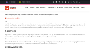
Website: darwinmotion.com
Darwin Motion manufactures Matrix series VFDs including Matrix-900, Matrix 350, Matrix 500, Matrix 680, and Matrix 880, designed for low, medium, and high voltage applications with focus on energy efficiency and process optimization. The text also references competing product lines: Siemens Sinamics series, Schneider Electric Altivar series, Yaskawa V1000 and A1000 series, Rockwell Automation Alle…

Industry’s Top 10 VFD Cable Manufacturers of 2023
Website: grandoceanmarine.com
The text provides market and technical details for Variable Frequency Drive (VFD) systems and specialized VFD cables used in industrial automation. Market data indicates the VFD market was valued at USD 3.2 billion in 2022 with projected CAGR growth through 2032, driven by industrial infrastructure transformation. Product specifications highlight that VFD cables are engineered to handle high volta…
B2B Engineering FAQs About Vfd Variable Frequency Drive
Q: How does the three-stage power conversion topology (Converter-DC Bus-Inverter) of a modern VFD impact Total Harmonic Distortion (THD) in solar pumping installations?
A: A standard 6-pulse VFD generates characteristic 5th, 7th, and 11th harmonics during the AC-to-DC conversion phase, where diode bridges create six current pulses per cycle. In solar pump inverters—such as Boray’s PV series—the DC bus section becomes particularly critical, as it must smooth both the rectified grid power (in hybrid systems) and the fluctuating PV array voltage while maintaining stable capacitor voltage for the IGBT inverter stage. For agricultural projects with long distribution lines, specify drives with built-in DC chokes or active front ends (AFE) to keep THD below 5%, preventing transformer overheating and utility penalties. In off-grid solar pumping, the absence of grid impedance makes DC bus stability entirely dependent on the VFD’s MPPT algorithm and capacitance sizing.
Q: When specifying a Solar Pump Inverter for high-altitude (≥1,000m) or desert installations, what derating factors must engineers apply beyond standard ampacity calculations?
A: Altitude derating is non-linear: above 1,000m, air density decreases by approximately 10% per 1,000m, reducing convective cooling efficiency and dielectric strength. Boray Inverter recommends derating VFD current capacity by 1% per 100m above 1,000m to prevent IGBT junction temperature excursions. For ambient temperatures exceeding 40°C, apply an additional 1.5% derating per degree Celsius. In solar pumping applications, also account for PV array voltage temperature coefficients—cold morning conditions can push open-circuit voltages above the VFD’s maximum DC input rating, requiring headroom in the DC bus voltage specification.
Q: How do MPPT algorithms in solar pump VFDs differ from standard grid-tied solar inverters, and why does this distinction matter for submersible pump starting torque?
A: Grid-tied inverters prioritize maximum power extraction from the PV array to feed the grid, whereas solar pump VFDs must balance MPPT efficiency with immediate motor torque demands. Submersible pumps require 150-200% starting torque to overcome static head and friction. Boray’s solar pump inverters utilize dynamic MPPT tracking that temporarily sacrifices optimal power point tracking during startup to maintain DC bus voltage stability, ensuring sufficient V/Hz ratio for high-breakaway torque. Once the pump reaches operating speed, the algorithm returns to standard perturb-and-observe MPPT. Engineers should verify that the VFD’s starting current limit (typically 150% for 60 seconds) aligns with the pump manufacturer’s NEMA torque curves.
Q: For EPC contractors integrating irrigation systems with SCADA, which communication protocols provide the best balance of real-time control and fault diagnostics for remote VFD monitoring?
A: For agricultural automation, Modbus RTU over RS485 remains the industry standard for distances up to 1,200m, offering sufficient bandwidth (19.2-115.2 kbps) for command speed, frequency reference, and fault code transmission. For larger solar farms requiring Ethernet infrastructure, Modbus TCP/IP or CANopen provide deterministic response times under 10ms—critical for multi-pump synchronization. Boray Inverters support both protocols natively, with optional GPRS/4G modules enabling cloud-based monitoring of parameters like DC bus voltage, output current, and IGBT temperature. Specify drives with embedded web servers for projects requiring browser-based diagnostics without dedicated SCADA software licenses.
Q: In variable torque pump applications, when should engineers specify Sensorless Vector Control (SVC) over traditional V/Hz control, and what are the efficiency implications?
A: V/Hz control maintains a constant volts-per-hertz ratio suitable for centrifugal pumps with stable load curves, offering simplicity and 95-96% efficiency at rated speed. However, for positive displacement pumps, deep well submersibles with high static head, or systems requiring precise pressure control via PID loops, SVC provides superior performance. SVC estimates rotor flux and torque current without encoder feedback, maintaining 0.5% speed accuracy and 150% starting torque at 0.5Hz. While SVC introduces approximately 2-3% additional switching losses due to higher carrier frequencies (4-8kHz vs 2-4kHz), the improved hydraulic efficiency in partial-load conditions typically yields 8-12% energy savings in variable-flow irrigation systems.
Q: How do input line reactors and dv/dt filters mitigate reflected wave phenomena in pump installations with motor cable runs exceeding 50 meters?
A: PWM inverter output creates steep-fronted voltage waves with rise times <0.1μs. When transmitted through long cables, impedance mismatches between the cable and motor create standing waves, potentially doubling voltage at the motor terminals (reflected wave theory). This stresses winding insulation and bearing currents. An input line reactor (3% impedance) reduces harmonic current draw and protects the DC bus capacitors, while a motor-side dv/dt filter (sine wave filter) slows voltage rise times to >0.5μs. For solar pump installations where pumps are 100m+ from inverters, specify filters rated for the specific carrier frequency, or consider bearing insulation kits for motors >100kW to prevent electrical fluting.
Q: What IP ratings and conformal coating specifications are mandatory for VFDs in humid, dusty, or chemically aggressive agricultural environments?
A: Standard IP20 enclosures suffice for climate-controlled electrical rooms, but outdoor solar pump installations require minimum IP54 (dust-protected, water splashing) or IP65 (dust-tight, water jets) ratings. In greenhouse or fertigation environments with ammonia or chlorine exposure, specify VFDs with IEC 60721-3-3 Class 3C2 or 3C3 conformal coating on PCBs—acrylic or polyurethane coatings that prevent conductive paths between traces during condensation cycles. Boray’s agricultural-grade drives utilize dual-layer conformal coating and sealed heat sinks with external fan cooling to prevent corrosive gas ingress while maintaining thermal performance. Always specify stainless steel enclosures for coastal solar installations to prevent salt spray corrosion.
Q: How should project engineers calculate payback periods when replacing Direct Online (DOL) starters with VFDs in centrifugal pumping systems, considering the Affinity Laws?
A: The Affinity Laws state that power consumption varies with the cube of pump speed (P ∝ N³) and flow varies linearly (Q ∝ N). For a pump operating at 80% flow, power drops to 51.2% (0.8³), yielding 48.8% energy savings. Calculate ROI using:
Annual Savings = (Motor HP × 0.746 kW/HP × Operating Hours × Energy Cost × (1 – (New Speed/Rated Speed)³)) – VFD Losses (3-4%)
For solar pumping, factor in avoided grid infrastructure costs and peak-demand charges. Typical payback periods range from 8-18 months for continuous-duty irrigation pumps >15kW. Boray’s energy calculation tools integrate local solar irradiance data to provide accurate LCOE (Levelized Cost of Energy) comparisons between AC grid, diesel, and solar VFD pumping solutions.
Disclaimer
⚠️ Important Disclaimer
The information provided in this guide is for educational purposes. Industrial applications and electrical engineering projects carry inherent risks. B2B buyers and contractors must conduct thorough technical due diligence and verify regional compliance before installation or procurement.
Conclusion: Partnering with Boray Inverter for Vfd Variable Frequency Drive
As industrial automation and renewable energy systems continue to evolve, the variable frequency drive remains the critical interface between electrical infrastructure and mechanical efficiency. Whether optimizing HVAC systems in commercial buildings, enabling precision control in manufacturing lines, or powering solar irrigation pumps in remote agricultural zones, VFD technology represents more than energy savings—it embodies operational resilience and sustainable engineering. The transition from fixed-speed motor operation to intelligent, frequency-controlled motion is no longer optional for competitive enterprises; it is the foundation of modern electromechanical strategy.
However, the performance of any VFD system ultimately depends on the engineering rigor and manufacturing precision of its source. This is where Shenzhen Boray Technology Co., Ltd. distinguishes itself as a strategic partner for global B2B clients. Operating from advanced facilities in China, Boray Inverter specializes in high-performance Solar Pumping and Motor Control Solutions designed specifically for demanding agricultural, irrigation, and industrial automation environments.
What sets Boray apart is an uncompromising commitment to technical innovation: our R&D team comprises 50% of the total workforce, driving continuous advancement in both Permanent Magnet Synchronous Motor (PMSM) and Induction Motor (IM) vector control technologies. These capabilities translate into VFD products that deliver superior torque response, enhanced energy efficiency, and robust performance across variable load conditions. Our manufacturing infrastructure features two modern production lines supported by 100% full-load testing protocols, ensuring that every unit shipped meets stringent international quality standards and field-ready reliability.
For EPC contractors, automation distributors, and agricultural project managers seeking more than off-the-shelf components, Boray offers engineered partnerships backed by deep expertise in motor control algorithms and solar pumping applications. We invite you to contact our technical team at borayinverter.com to discuss customized VFD configurations, OEM opportunities, and competitive wholesale quotations tailored to your specific application requirements.