Introduction: Sourcing Variable Frequency Drive Induction Motor for Industrial Use
In industrial environments where electric motors account for nearly 70% of total energy consumption, the mismatch between fixed-speed induction motors and variable operational demands represents one of the most significant inefficiencies in modern automation. Whether driving centrifugal pumps in water treatment facilities, conveyors in material handling, or solar-powered irrigation systems in remote agricultural deployments, induction motors traditionally operate at constant speed regardless of load—wasting energy through mechanical throttling, excessive inrush currents, and unnecessary full-speed operation. Variable Frequency Drives (VFDs) eliminate this waste by dynamically adjusting frequency and voltage to match motor speed with real-time process requirements, delivering energy savings of up to 50% in variable torque applications while extending equipment lifespan through soft-start capabilities and precise process control.
For EPC contractors, automation distributors, and agricultural project managers sourcing motor-drive solutions, selecting the optimal VFD-induction motor pairing requires navigating complex technical specifications—from voltage classes (110V single-phase to 575V three-phase) and horsepower ranges (0.25–300 HP) to control methodologies (V/f, sensorless vector, closed-loop vector) and environmental protection ratings. This is particularly critical in solar pumping applications, where DC-to-AC conversion efficiency, MPPT compatibility, and off-grid operational stability directly impact system ROI and long-term reliability.
This comprehensive guide examines the complete sourcing landscape for VFD-controlled induction motors, detailing motor types (squirrel cage vs. wound rotor), drive topologies, key specification parameters for industrial and agricultural use, and evaluation criteria for global manufacturers. Whether specifying equipment for conveyor systems, HVAC retrofits, or off-grid solar irrigation projects, understanding these integration points ensures optimal performance, energy efficiency, and operational longevity across your automation infrastructure.
Article Navigation
- Top 4 Variable Frequency Drive Induction Motor Manufacturers & Suppliers List
- Introduction: Sourcing Variable Frequency Drive Induction Motor for Industrial Use
- Technical Types and Variations of Variable Frequency Drive Induction Motor
- Key Industrial Applications for Variable Frequency Drive Induction Motor
- Top 3 Engineering Pain Points for Variable Frequency Drive Induction Motor
- Component and Hardware Analysis for Variable Frequency Drive Induction Motor
- Manufacturing Standards and Testing QC for Variable Frequency Drive Induction Motor
- Step-by-Step Engineering Sizing Checklist for Variable Frequency Drive Induction Motor
- Wholesale Cost and Energy ROI Analysis for Variable Frequency Drive Induction Motor
- Alternatives Comparison: Is Variable Frequency Drive Induction Motor the Best Choice?
- Core Technical Specifications and Control Terms for Variable Frequency Drive Induction Motor
- Future Trends in the Variable Frequency Drive Induction Motor Sector
- B2B Engineering FAQs About Variable Frequency Drive Induction Motor
- Disclaimer
- Conclusion: Partnering with Boray Inverter for Variable Frequency Drive Induction Motor
Technical Types and Variations of Variable Frequency Drive Induction Motor
Variable frequency drives for induction motors are not monolithic; they vary significantly by input topology, control algorithm, and environmental hardening. Selecting the appropriate configuration is critical for optimizing energy efficiency—particularly in solar pumping applications where DC bus architecture and Maximum Power Point Tracking (MPPT) capabilities determine system viability. Below, we categorize the primary technical variations relevant to industrial automation and agricultural electrification projects.
| Type | Technical Features | Best for (Industry) | Pros & Cons |
|---|---|---|---|
| Solar DC-to-AC VFD (PV Pump Drive) | • DC input voltage range (200V–800V) • Integrated MPPT algorithm • Battery-less or hybrid DC bus architecture • V/f or open-loop vector control • Dry-run and water level protection |
Agriculture, remote irrigation, livestock watering, off-grid water supply | Pros: Eliminates grid dependency; 30–50% energy savings via affinity laws; operates during daylight without battery storage. Cons: Output fluctuates with irradiance; requires oversized PV array for morning/evening torque demands; limited functionality in low-light conditions. |
| Grid-Tied General Purpose VFD (3-Phase AC) | • Input: 380–480V or 575V AC 3-phase • Diode/IGBT rectifier front-end • V/f control standard; vector control optional • Dynamic braking chopper capability • Modbus/Profibus communication |
Manufacturing, HVAC, water treatment, conveyor systems | Pros: Mature technology; broad power range (0.25–300+ HP); regenerative braking options available. Cons: High inrush current (6–8x FLA) during DOL bypass requires 2x FLA sizing for high-torque starts; harmonic distortion on supply grid without line reactors. |
| Single-Phase Input VFD (Phase Converter) | • Input: 110V or 240V single-phase • Output: 3-phase 220V/380V (derated) • Capacitor doubler or active PFC front-end • Compact design for NEMA 1/12 enclosures • Built-in EMI filtering |
Rural agriculture, small workshops, retrofitting legacy single-phase sites | Pros: Converts single-phase grid to 3-phase motor power without rotary phase converters; cost-effective for <10 HP applications. Cons: 30–50% output current derating required; limited to smaller motors; reduced lifespan if run near maximum rated ambient temperature. |
| Vector Control VFD (Sensorless/Closed-Loop) | • Sensorless vector (SLV) or flux vector control • 0.5 Hz high torque start (150% rated torque) • Auto-tuning for motor parameter identification • Speed regulation ±0.5% (SLV) or ±0.01% (closed-loop) • Torque control mode for winding/unwinding |
Extruders, CNC machine tools, hoists, high-precision pumps, test stands | Pros: Precise torque control independent of speed; excellent low-speed performance; compensates for load fluctuations. Cons: Higher cost; requires motor data plate parameters for auto-tuning; closed-loop variants need encoder/ resolver installation. |
| IP65/Outdoor Hardened VFD | • Die-cast aluminum housing with conformal coating • Operating temp: -20°C to +60°C (with derating) • Built-in DC reactor for harmonic mitigation • Direct wall or motor-mount capability • UV-resistant cable glands and sealing |
Outdoor irrigation, dusty quarries, marine environments, food processing (washdown) | Pros: Eliminates need for separate enclosure; withstands direct solar load and thermal cycling; protects against dust/condensation. Cons: Limited heat dissipation compared to panel-mount units; heavier weight; restricted access to terminal blocks for field wiring. |
Solar DC-to-AC VFD (PV Pump Drive)
Solar pump inverters represent a specialized subclass where the DC bus is fed directly from photovoltaic arrays rather than a rectified AC grid. These drives utilize MPPT algorithms to maintain the DC voltage at the array’s maximum power point, ensuring optimal energy harvest even during fluctuating irradiance. For induction motor applications, the inverter must provide sufficient starting torque (typically 150% rated torque) at low solar irradiance, necessitating careful PV array oversizing or battery-buffered hybrid designs. Unlike grid-tied systems, these VFDs often incorporate specialized protection logic for dry-run detection and water tank level management, critical for borehole pumps in remote agricultural deployments.
Grid-Tied General Purpose VFD (3-Phase AC)
The standard industrial workhorse, these drives convert fixed-frequency grid power to variable frequency/voltage output via a rectifier-DC bus-inverter topology. For high-inertia applications such as screw feeders or thermal processors, engineering specifications must account for the 2x full-load amp (FLA) sizing rule to accommodate the high inrush current during startup—failure to size correctly results in overcurrent faults or premature DC bus capacitor failure. Modern units offer V/f control for variable torque loads (pumps/fans) where the cube-law affinity relationship enables dramatic energy savings, or vector control for constant torque demands.
Single-Phase Input VFD (Phase Converter)
In rural electrification contexts where three-phase infrastructure is unavailable, these drives accept single-phase input (110V or 240V) and synthesize three-phase output through a voltage doubler circuit. Critical engineering considerations include mandatory derating—typically to 50% of the drive’s nominal three-phase current rating—to prevent overheating of the input rectifier and DC bus capacitors. These units are ideal for small-scale agricultural processing equipment (grain augers, small mixers) but are unsuitable for continuous-duty high-torque applications due to thermal limitations.
Vector Control VFD (Sensorless/Closed-Loop)
Moving beyond basic V/f control, vector drives decouple torque and flux components to provide dynamic response comparable to DC drives. Sensorless vector control estimates rotor position via current feedback, eliminating encoder hardware while maintaining 0.5% speed accuracy—sufficient for most pump and fan applications. Closed-loop vector control, utilizing encoder feedback, achieves ±0.01% speed regulation and full torque at zero speed, essential for positioning applications or high-precision extrusion processes. The auto-tuning function identifies motor stator resistance and inductance parameters, critical for maintaining efficiency across the speed range.
IP65/Outdoor Hardened VFD
Designed for harsh environmental conditions, these drives feature die-cast aluminum heat sinks with conformal-coated PCBs to resist moisture, dust, and chemical exposure. In solar pumping installations, wall-mounted IP65 units eliminate the cost and space requirements of NEMA 3R/4 enclosures. Thermal management relies on natural convection or fan-cooled heat sinks with dust filters; however, ambient temperatures exceeding 40°C require current derating to prevent IGBT junction temperature overshoot. Direct motor-mount configurations reduce electromagnetic interference (EMI) by minimizing cable lengths between drive and motor terminals.
Key Industrial Applications for Variable Frequency Drive Induction Motor
Variable Frequency Drives (VFDs) paired with induction motors form the backbone of modern industrial automation and renewable energy systems. By enabling precise speed control, soft-start capabilities, and significant energy optimization, these systems address the operational inefficiencies inherent in constant-speed motor applications. For EPC contractors and automation engineers, selecting the appropriate VFD-induction motor configuration requires understanding sector-specific load profiles—from the variable torque demands of centrifugal pumps to the constant torque requirements of conveyors and crushers.
| Sector | Application | Energy Saving Value | Sourcing Considerations |
|---|---|---|---|
| Agriculture & Solar Irrigation | Solar pump inverters driving submersible and surface induction motors for drip irrigation, center-pivot systems, and livestock water supply | 30–50% reduction in energy costs compared to grid-tied DOL systems; elimination of diesel generator dependency; optimized water flow matching actual crop evapotranspiration rates | IP65/NEMA 4X enclosures for outdoor UV exposure and dust; wide MPPT voltage range (200V–800V DC) for PV array compatibility; anti-islanding and dry-run protection algorithms; V/f control optimized for pump curves; automatic sleep/wake functions based on solar irradiance |
| Water & Wastewater Treatment | Centrifugal pumps, aeration blowers, and filtration systems in municipal plants and industrial effluent treatment | 40–60% energy savings via affinity laws (power proportional to speed cubed); reduced mechanical seal wear and cavitation damage; precise dissolved oxygen control in aeration basins | Stainless steel or epoxy-coated heat sinks for corrosive H₂S environments; built-in DC chokes or active front ends for IEEE 519 compliance; Modbus RTU/TCP or Profibus DP communication for SCADA integration; PID control loops for constant pressure/flow regulation |
| HVAC & Building Automation | Chilled water circulation pumps, cooling tower fans, air handling units (AHUs), and secondary pumping stations | 30–45% reduction in HVAC energy consumption; elimination of mechanical throttling valves and damper losses; acoustic optimization through variable carrier frequency | BACnet MS/TP or LonWorks protocol support; Class A EMC filters to prevent interference with BMS sensors; fire mode override functionality; multi-pump cascade control for staging/destaging; automatic energy optimization (AEO) algorithms |
| Mining & Cement Processing | Belt conveyors, ball mills, crushers, rotary kilns, and stacker-reclaimers | 15–25% energy savings through load-sharing and soft-start ramp control (eliminating 6–8x inrush current); reduced mechanical stress on gearboxes and couplings; extended motor insulation life | Heavy-duty chassis with conformal coating (3C3 or 3C4 environment class); dynamic braking units or regenerative front ends for high-inertia loads; derating factors for altitude >1000m and 50°C ambient; flux vector control for 150% starting torque at 0.5Hz; STO (Safe Torque Off) safety integrated functions |
| Food & Beverage Manufacturing | Screw feeders, thermal processors, mixers, extruders, and packaging line conveyors | 20–35% energy reduction via volumetric metering precision; reduced product waste through accurate residence time control in thermal processors; gentle handling of shear-sensitive materials | Food-grade IP54/IP66 stainless steel enclosures; washdown-duty ratings (resistance to high-pressure jets); safe torque-off (STO) and SS1 safety functions; parameter backup/restore for quick recipe changeover; compatibility with single-phase 220V and three-phase 380–480V motors |
Agriculture & Solar Irrigation
In off-grid and grid-tie agricultural operations, solar pump inverters convert DC photovoltaic power to variable-frequency AC to drive induction motors in submersible borehole pumps and surface irrigation systems. Unlike traditional DOL (Direct-On-Line) starters, VFDs enable soft starting that eliminates voltage dips and mechanical water hammer. When sourcing these systems, engineers must verify the inverter’s MPPT voltage window aligns with the PV array’s open-circuit voltage (Voc) and maximum power point voltage (Vmp). Critical protection features include dry-run detection (using power curve analysis or float switches) and automatic restart after fault conditions. For large-scale EPC projects, specify VFDs with IP65 enclosures and conformal-coated PCBs to withstand humidity, dust, and rodent ingress common in rural installations.
Water & Wastewater Treatment
Municipal pumping stations and aeration basins represent ideal variable torque applications where the affinity laws govern energy consumption. Reducing pump speed by 20% yields approximately 50% power savings, making VFDs mandatory for Energy Service Company (ESCO) retrofits. When specifying drives for this sector, prioritize units with built-in DC link chokes or active front ends to mitigate harmonic distortion that can disrupt sensitive PLC and SCADA networks. For aeration blowers, select VFDs with advanced PID control to maintain dissolved oxygen setpoints, automatically adjusting blower speed based on real-time demand rather than cycling motors on/off. Corrosion-resistant heat sinks and sealed enclosures (NEMA 4X) are essential for biogas-rich environments.
HVAC & Building Automation
Commercial building systems benefit from VFDs through variable flow hydronics and air distribution. In chilled water systems, secondary pumps with VFDs enable differential pressure control, reducing pumping energy during part-load conditions. Cooling tower fans utilize the same cube-law efficiency gains as pumps. Sourcing considerations for building automation include open-protocol communication (BACnet or Modbus) for seamless integration with Building Management Systems (BMS), as well as EMC compliance to prevent interference with fire alarm and security systems. Fire mode override—a dedicated input that forces the drive to run at preset speed regardless of faults—is a critical safety requirement for smoke evacuation and pressurization applications.
Mining & Cement Processing
Heavy-industry applications involve constant torque loads and high-inertia machinery where induction motors face extreme mechanical stress during direct starting. VFDs provide controlled acceleration ramps (typically 10–60 seconds) that limit inrush current to 1.5x rated current, preventing voltage sags that disrupt mine-wide power distribution. For crushers and ball mills, specify drives with flux vector control or direct torque control (DTC) to deliver 150–200% starting torque at low speeds without encoder feedback. High-altitude derating is crucial for mining operations above 1000 meters, as reduced air density decreases cooling capacity. Additionally, specify braking resistors or regenerative units for downhill conveyors and high-inertia loads to dissipate or recover deceleration energy.
Food & Beverage Manufacturing
Screw feeders and thermal processors—common in food processing—require precise speed control for volumetric metering and residence time management. VFDs allow operators to fine-tune discharge rates without mechanical gear changes. In these hygienic environments, specify drives with IP66/NEMA 4X stainless steel enclosures that withstand caustic washdown chemicals and high-pressure spray. Safety functions such as Safe Torque Off (STO) according to IEC 61800-5-2 are essential for compliance with machinery directives, allowing immediate removal of motor torque during cleaning or maintenance operations. Parameter cloning capabilities via removable keypads or PC software facilitate rapid commissioning of multiple identical conveyors or mixers on packaging lines.
Top 3 Engineering Pain Points for Variable Frequency Drive Induction Motor
When integrating Variable Frequency Drives with induction motors in industrial automation and solar pumping infrastructure, engineers must navigate specific technical constraints that directly impact system reliability, energy yield, and total cost of ownership. The following three scenarios represent the most critical engineering challenges faced by EPC contractors and agricultural project managers when specifying motor control solutions.
Scenario 1: Destabilizing Inrush Currents and Grid Voltage Sag
The Problem: Direct-on-line (DOL) starting of induction motors generates severe inrush currents—typically six to eight times the rated full-load amperage—creating immediate voltage sags across the distribution network. In solar pumping installations with limited DC bus capacity or weak rural grid connections, these transients can trigger protective relay trips, destabilize inverter synchronization, and impose mechanical shock on couplings and bearings. As observed in high-torque conveying applications, the brief but intense starting current often necessitates oversizing distribution transformers and switchgear merely to accommodate startup events rather than continuous operational loads, increasing capital expenditure without improving efficiency.
The Solution: VFDs eliminate inrush current through controlled voltage-frequency ramps, limiting starting current to nominal rated values while providing full torque availability. For high-inertia or high-torque applications such as screw feeders, deep-well solar pumps, or thermal processors, specify drives sized for at least twice the motor’s full-load amps to handle startup demands without voltage disturbance. Advanced flux vector control algorithms optimize magnetic flux maintenance during acceleration, protecting mechanical transmission components from torsional shock while maintaining grid stability—critical for agricultural projects operating on generator backup or solar hybrid systems where power quality is non-negotiable.
Scenario 2: Energy Waste in Variable Torque Applications
The Problem: Fixed-speed induction motors driving centrifugal pumps and fans operate at constant frequency regardless of actual process demand, forcing operators to rely on throttling valves or dampers for flow control. This approach maintains near-full power consumption while wasting mechanical energy as heat and pressure loss. In variable torque applications where systems only require 60–70% of rated flow for significant operational periods, the affinity laws demonstrate that power consumption follows the cube of speed—meaning a 20% reduction in motor speed can lower power consumption by nearly 50%, yet fixed-speed operation forfeits these gains entirely, converting valuable electrical energy into parasitic heat.
The Solution: Implement VFDs to modulate motor speed in direct response to process variables (pressure, flow, temperature), eliminating throttling losses and mechanical restriction devices. By adjusting output frequency and voltage while maintaining optimal V/f ratios or utilizing sensorless vector control, the drive ensures the induction motor consumes only the energy required for instantaneous load conditions. This is particularly vital for solar pumping systems where photovoltaic array capacity is finite; matching motor speed to real-time solar irradiance levels maximizes daily water throughput while preventing array voltage collapse. Modern VFDs with integrated PID controllers and multi-pump control algorithms enable precise process management without external PLC hardware, reducing system complexity and points of failure.
Scenario 3: Environmental Degradation and Long-Distance Power Transmission
The Problem: VFD installations in agricultural and remote solar pumping environments face extreme thermal cycling, dust infiltration, and humidity—conditions that accelerate electrolytic capacitor degradation and semiconductor failure in standard IP20-rated drives. Furthermore, the PWM output waveforms from VFDs, combined with long cable runs between surface-mounted inverters and submersible motors, create voltage reflection phenomena that can exceed motor insulation ratings. These fast-switching transients also induce shaft voltages and bearing currents, leading to electrical discharge machining (EDM) pitting in motor bearings and premature mechanical failure in locations where service access is difficult and maintenance costs are prohibitive.
The Solution: Specify VFDs with IP65 or IP66-rated aluminum enclosures featuring conformal-coated PCBs and isolated cooling channel designs to prevent dust and moisture ingress while managing thermal derating in ambient temperatures exceeding 40°C. For submersible motor applications or installations requiring cable runs exceeding 50 meters, utilize VFDs with built-in dv/dt filters or sine wave output reactors to mitigate voltage reflection and reduce common-mode currents that damage motor bearings. Additionally, drives should offer flexible mounting configurations—direct-to-motor, wall-mounted, or centralized control panel installation—to separate sensitive electronics from harsh field conditions while maintaining communication capability via RS485 or Ethernet protocols for remote monitoring and predictive maintenance diagnostics.
Component and Hardware Analysis for Variable Frequency Drive Induction Motor
The reliability and efficiency of a Variable Frequency Drive (VFD) induction motor system are fundamentally determined by the quality of its internal hardware architecture. For industrial engineers and EPC contractors deploying solutions in harsh environments—such as solar pumping stations with wide temperature fluctuations, agricultural sites with dust and humidity, or continuous-process manufacturing—understanding the component-level construction is essential for assessing Total Cost of Ownership (TCO) and Mean Time Between Failures (MTBF).
Power Semiconductor Stage: IGBT Modules
At the heart of every VFD lies the Insulated Gate Bipolar Transistor (IGBT) module, responsible for pulse-width modulation (PWM) switching to synthesize variable frequency output. In solar pump inverter applications, where DC input voltage varies significantly with irradiance levels, IGBTs must withstand elevated voltage stresses and thermal cycling. Premium drives utilize Trench-Stop or Field-Stop IGBT technology with low Vce(sat) characteristics to minimize conduction losses. The thermal resistance (Rth(j-c)) between junction and case is a critical specification; values below 0.15 K/W indicate superior heat dissipation capability, directly correlating with extended operational life under high-switching-frequency conditions required for precise induction motor control.
Control Architecture: DSP and Microprocessors
Modern VFDs employ Digital Signal Processors (DSPs) or ARM-based microcontrollers to execute complex vector control algorithms in real-time. For induction motor applications requiring dynamic torque response—such as conveyor systems or deep-well solar pumps—processing speeds above 40 MIPS (Million Instructions Per Second) ensure accurate flux vector orientation and slip compensation. Hardware quality indicators include industrial-grade temperature specifications (-40°C to +85°C ambient operation) and integrated hardware-based protection logic that operates independently of software loops, ensuring immediate fault response during overcurrent or ground fault events.
Thermal Management Systems
Thermal design separates industrial-grade VFDs from commercial alternatives. The heatsink assembly—typically aluminum extrusion with copper baseplates in high-performance units—must maintain thermal resistance below 0.5 °C/W for the power stage. Critical quality factors include anodized surfaces to prevent oxidation in outdoor solar installations, and thermal interface materials (TIMs) with phase-change properties to ensure consistent heat transfer from IGBT baseplates to the heatsink. For forced-air cooled units, ball-bearing fans with IP54 or higher protection ratings and L10 life ratings exceeding 50,000 hours are essential; sleeve bearings often fail prematurely in agricultural environments with high dust concentrations.
Energy Storage and DC-Link Capacitors
The DC bus capacitor bank filters ripple current from the rectifier and provides energy storage during input voltage sags. In solar pump applications where input voltage fluctuates with cloud transients, film capacitors (polypropylene metallized film) offer superior longevity compared to electrolytic alternatives, with rated lives exceeding 100,000 hours at maximum operating temperatures. Key quality indicators include ripple current capacity (Irms), equivalent series resistance (ESR), and self-healing properties. Electrolytic capacitors, while cost-effective, suffer from electrolyte evaporation; premium drives specify 105°C-rated units with calculated lifespans based on Arrhenius equations for temperature derating.
Input Protection and EMI Suppression
The input stage comprises rectifier bridges—often three-phase full-wave configurations—and EMI filters to suppress conducted emissions. For induction motor drives operating on weak grid infrastructure or solar DC inputs with high impedance, rectifier bridges must withstand surge currents exceeding 300% rated current during capacitor charging events. Common-mode and differential-mode chokes with high-permeability ferrite cores prevent interference with nearby automation equipment, a critical consideration for integrated pumping stations with SCADA systems.
Component Quality Analysis Table
| Component | Function | Quality Indicator | Impact on Lifespan |
|---|---|---|---|
| IGBT Power Module | Converts DC bus voltage to variable frequency AC via PWM switching | Junction temperature rating (Tj max >150°C), Thermal resistance Rth(j-c) <0.15 K/W, Trench-Stop technology | Critical – Thermal cycling and switching losses cause bond wire fatigue; primary failure mode in high-duty applications |
| DC Bus Capacitor | Filters rectifier output ripple and stores energy for motor inrush | Ripple current capacity (Irms), Film dielectric vs. Electrolytic, 105°C rated life >100,000 hrs | Very High – Electrolyte evaporation in electrolytic types; film capacitors offer 3-5x lifespan in solar applications |
| DSP/Controller | Executes V/f or vector control algorithms, manages protection logic | Clock speed >40 MIPS, Industrial temp range (-40°C to +85°C), Hardware watchdog circuits | Medium – Generally robust; failures usually secondary to voltage spikes or moisture ingress |
| Heatsink Assembly | Dissipates semiconductor switching losses to ambient | Thermal resistance <0.5 °C/W, Anodized aluminum or copper composite construction, Phase-change TIM | High – Insufficient cooling accelerates semiconductor aging; thermal runaway risk if clogged in dusty environments |
| Rectifier Bridge | Converts AC line input to DC (or manages DC input protection) | Surge current rating (IFSM), Reverse voltage rating (VRRM) with 2x safety margin, Thermal capacity | Medium-High – Vulnerable to grid voltage transients; quality units include integrated thermistors |
| Current Sensors | Provides real-time phase current feedback for vector control and overcurrent protection | Accuracy ±0.5%, Bandwidth >50kHz, Galvanic isolation >2.5kV | Medium – Hall-effect sensors drift over time; shunt resistors more stable but require isolation amplifiers |
| EMI Filter | Suppresses conducted and radiated electromagnetic interference | Insertion loss >60dB at switching frequency, Current rating with 1.5x safety margin, High-voltage pulse withstand | Low-Medium – Capacitor degradation affects performance but rarely causes catastrophic failure; critical for CE/UL compliance |
| Cooling Fan | Forced air convection for heatsink (in forced-cooled designs) | Ball-bearing construction, MTBF >50,000 hrs (L10), IP54 minimum rating, Tachometer feedback | High – Bearing failure is leading cause of VFD thermal shutdown; sleeve bearings unsuitable for agricultural/industrial duty |
Integration Considerations for Solar Pumping Applications
In photovoltaic-powered induction motor systems, component selection requires additional scrutiny. The absence of grid buffering means VFDs must tolerate rapid input voltage swings from 200V to 800V DC depending on array configuration and irradiance. IGBT modules rated for 1200V rather than 600V provide necessary headroom, while DC-link capacitors must handle high ripple currents during maximum power point tracking (MPPT) fluctuations. Encapsulated PCBs with conformal coating (IPC-CC-830 Class 3) prevent moisture ingress in outdoor enclosures, protecting DSP controllers and gate driver circuits from humidity-induced corrosion common in irrigation environments.
For EPC contractors evaluating VFD hardware, specifying components with industrial-grade temperature ratings and demonstrated thermal management capabilities ensures that induction motor systems achieve the 15-20 year operational lifespans required for solar infrastructure investments, minimizing replacement cycles in remote agricultural installations.
Manufacturing Standards and Testing QC for Variable Frequency Drive Induction Motor
Ensuring long-term reliability in variable frequency drive (VFD) and induction motor systems begins at the component sourcing stage and extends through rigorous factory acceptance testing. For applications ranging from agricultural solar pumping to continuous industrial automation, substandard manufacturing processes result in premature failure of IGBT modules, DC bus capacitors, and control PCBs—particularly when deployed in harsh outdoor environments with high humidity, dust, and temperature fluctuations.
Component-Level Environmental Protection
High-reliability VFD manufacturing starts with PCB assembly standards that exceed standard consumer electronics specifications. For solar pump inverters and industrial motor drives, conformal coating of all control circuit boards is mandatory rather than optional. This acrylic or silicone-based protective layer creates a dielectric barrier against moisture ingress and conductive dust, critical for agricultural installations where drives may operate in 95% relative humidity or exposed to chemical fertilizers. Leading manufacturers utilize automated selective coating processes followed by UV fluorescence inspection to ensure complete coverage of solder joints and trace patterns without compromising thermal dissipation through heat sink interfaces.
Thermal Stress Validation and Burn-In Protocols
Before final assembly, power components undergo high-temperature aging (HTA) cycles that simulate decade-long operational stress. IGBT modules and DC link film capacitors are subjected to 85°C ambient thermal cycling for 72–168 hours under dynamic load conditions to identify early-life failures (infant mortality). This process, combined with thermal shock testing between -40°C and +85°C, validates solder joint integrity and thermal interface material stability. For solar pumping applications where drives experience rapid temperature swings between cool mornings and peak solar irradiance, this screening eliminates field failures caused by thermal expansion mismatches between ceramic substrates and aluminum heat sinks.
100% Full-Load Production Testing
Unlike consumer electronics where sampling inspection suffices, industrial VFDs require 100% full-load testing at rated current and maximum ambient temperature. Each unit undergoes a minimum 2-hour burn-in at 100% rated load with the inverter driving a matched induction motor to verify:
– Output current waveform symmetry and THD (Total Harmonic Distortion) compliance with IEC 61000-3-6
– Thermal runaway protection activation thresholds
– Dynamic braking chopper functionality
– Phase-loss detection and ride-through capability
For solar pump inverters, additional testing includes MPPT (Maximum Power Point Tracking) efficiency verification across 200V–800V DC input ranges to ensure compatibility with fluctuating photovoltaic array outputs. Units are tested under simulated partial shading conditions to verify anti-islanding protection and grid-code compliance for export markets.
Electromagnetic Compatibility and Safety Certification
Manufacturing facilities must maintain ISO 9001:2015 quality management systems with documented traceability for all semiconductor components. CE marking compliance requires comprehensive EMC testing including:
– Radiated emission suppression (EN 61800-3 Category C2/C3)
– Conducted immunity to voltage dips and interruptions (IEC 61000-4-11)
– ESD protection verification (IEC 61000-4-2 Level 3/4)
For EPC contractors and automation distributors, access to detailed factory test reports—including hipot testing (2kV AC for 1 minute between mains and earth), insulation resistance measurements (>100MΩ), and efficiency curves across the V/f control range—provides necessary documentation for project commissioning and warranty validation.
Solar-Specific Durability Standards
Given Boray Inverter’s specialization in solar pumping systems, manufacturing protocols incorporate IP65 or IP66 enclosure integrity testing using pressurized water jets and dust exposure chambers (IEC 60529). UV-resistant ABS or powder-coated aluminum housings prevent degradation in direct solar exposure, while conformal-coated PCBs resist the corrosive effects of agricultural chemicals. Each drive undergoes vibration testing (5–55Hz, 0.15mm amplitude) to simulate transportation stress and pumping station mechanical resonance.
These manufacturing standards ensure that whether deployed in remote agricultural irrigation projects or continuous-duty industrial conveyors, the VFD maintains precise speed control while minimizing energy consumption through optimized V/f curves and sensorless vector control algorithms—delivering the reliability that global automation engineers and solar EPC contractors require for 20-year operational lifespans.
Step-by-Step Engineering Sizing Checklist for Variable Frequency Drive Induction Motor
Proper sizing of a Variable Frequency Drive (VFD) for induction motor applications—particularly in solar pumping and heavy industrial automation—requires rigorous adherence to electrical engineering principles beyond simple horsepower matching. Undersizing leads to nuisance tripping and premature failure, while oversizing reduces power factor and control precision. The following protocol provides a systematic framework for EPC contractors, automation distributors, and project engineers to ensure optimal compatibility between the motor, mechanical load, power source, and drive topology.
1. Motor Nameplate Data Verification and Insulation Assessment
Before selecting the VFD, extract and validate all critical parameters from the motor nameplate:
- Full Load Amps (FLA): Record the rated current at the specified voltage and frequency. For motors intended for inverter duty, confirm the insulation class (Class F or H preferred) and verify the manufacturer’s rating for inverter-fed operation.
- Service Factor (SF): If the application demands intermittent overloads (e.g., conveyor start-up under load), account for the service factor (typically 1.15). The VFD must support the motor’s SF current without thermal derating.
- Base Speed and Pole Count: Calculate the synchronous speed (Ns = 120f/P) to ensure the VFD’s output frequency range (typically 0–400 Hz) accommodates the required operating speed envelope without field weakening complications.
- Cooling Method: For constant torque applications below 30% of base speed, confirm the motor utilizes independent forced ventilation (separate cooling fan) rather than shaft-mounted fans to prevent thermal damage.
2. Load Characterization and Torque Profile Analysis
Characterize the mechanical load to determine the required VFD control algorithm and current capacity:
- Variable Torque (Centrifugal) Loads: For pumps and fans, apply the Affinity Laws: power varies with the cube of speed (P ∝ n³). A 20% reduction in speed yields approximately 50% energy savings. Size the VFD based on the motor FLA at maximum speed, but verify the drive’s minimum speed can maintain adequate cooling or bearing lubrication.
- Constant Torque Loads: For conveyors, screw feeders, and compressors, torque remains constant across the speed range. Critical Sizing Rule: As demonstrated in high-inrush applications like screw feeders, size the VFD for at least 2 times the motor’s FLA to accommodate the high starting current and prevent overcurrent trips during material engagement.
- High Inertia Loads: Calculate the total inertia (GD²) reflected to the motor shaft. If deceleration time is less than the mechanical time constant, specify dynamic braking resistors or regenerative units to prevent DC bus overvoltage.
3. VFD Current Rating and Overload Capacity Calculation
Select the drive based on continuous and transient current requirements, not just kW/HP ratings:
- Continuous Current: The VFD’s rated output current must equal or exceed the motor’s FLA at the lowest expected ambient temperature.
- Overload Capacity: Verify the drive’s overload rating (typically 150% of rated current for 60 seconds and 200% for 3 seconds). For heavy-starting loads, ensure the 150% overload duration exceeds the motor’s acceleration time.
- Switching Frequency: Higher carrier frequencies (8–16 kHz) reduce motor noise but increase drive heating. Derate the VFD current by 5–10% for each 1 kHz increase above the base frequency if operating near thermal limits.
4. Voltage Compatibility and Power Quality Analysis
Ensure electrical compatibility across the system architecture:
- Input Voltage Matching: Confirm the VFD’s input voltage range accommodates site conditions. Standard industrial drives accept three-phase 380–480V ±10%, while solar pump inverters require DC input ranges (typically 200–800VDC or 350–1000VDC depending on model).
- Output Voltage/Frequency Control: For standard induction motors, maintain the Volts-per-Hertz (V/f) ratio constant below base speed to prevent flux saturation. For high-starting-torque applications, select drives with sensorless vector control or closed-loop vector control to maintain torque at low speeds.
- Harmonic Mitigation: For installations >50 HP, calculate Total Harmonic Distortion (THD). Specify line reactors or DC link chokes (3% impedance) to reduce current harmonics and protect upstream transformers.
5. Solar Array String Configuration (for PV-Powered Systems)
When deploying solar pump inverters, the PV array sizing determines system viability:
- Voltage Window Calculation: Calculate the open-circuit voltage (Voc) at the lowest expected temperature (using temperature coefficient -0.3%/°C to -0.5%/°C) to ensure it never exceeds the inverter’s maximum DC input voltage. Simultaneously, verify the maximum power point voltage (Vmp) at the highest cell temperature remains above the inverter’s minimum MPPT voltage threshold.
- Power Sizing Ratio: Size the PV array wattage at 1.3 to 1.5 times the motor’s rated power to account for irradiance variability, temperature derating, and inverter efficiency losses. For example, a 7.5 kW motor requires approximately 10–11 kWp of PV capacity.
- String Configuration: Arrange panels in series to achieve Vmp within the inverter’s MPPT window (e.g., 400–800VDC), and parallel strings to achieve required current capacity. Ensure the short-circuit current (Isc) does not exceed the inverter’s maximum DC input current per MPPT channel.
6. Environmental Derating and Enclosure Specifications
Adjust ratings for installation environment:
- Altitude Derating: Above 1,000 meters (3,300 feet), reduce VFD current capacity by 1% per 100 meters due to reduced air density and cooling efficiency. Above 2,000 meters, consider external cooling or cabinet pressurization.
- Temperature Derating: If ambient temperature exceeds 40°C (104°F), derate the drive by 2–3% per degree Celsius, or specify high-temperature rated units (50°C capability).
- Ingress Protection: For agricultural or dusty environments, specify IP55 or IP66 enclosures for wall-mounted drives, or install within IP54 control panels with positive pressure ventilation.
7. Protection Coordination and Cable Sizing
Ensure safety and electromagnetic compatibility:
- Input Protection: Size circuit breakers or fuses at 1.5 to 2.0 times the VFD’s input current rating, with Type 2 coordination (semiconductor fuses) for short-circuit protection without drive damage.
- Output Cable Sizing: Size motor cables based on the VFD’s rated output current, not the motor FLA. Use shielded cables (XLPE insulation) with continuous aluminum or copper shields grounded at both ends to mitigate bearing currents and EMI.
- Grounding: Implement dedicated PE conductors and ensure low-impedance grounding (<0.1Ω) to prevent common-mode voltage issues.
8. Control Interface and Communication Protocols
Define the automation architecture:
- I/O Verification: Confirm sufficient digital inputs (start/stop, fault reset), analog inputs (0–10V or 4–20mA for speed reference), and relay outputs (fault indication). For solar pumps, verify inputs for water level sensors and float switches.
- Network Compatibility: Specify communication protocols (Modbus RTU/TCP, CANopen, or Profinet) for SCADA integration. Ensure the VFD supports remote monitoring capabilities essential for distributed solar pumping stations.
- PID Control: For closed-loop pressure or flow control, verify built-in PID functionality with sleep/wake functions to prevent pump cycling and energy waste during low-demand periods.
9. Commissioning Validation Checklist
Before final acceptance testing, verify:
- Parameter Upload: Record motor nameplate data into the VFD (rated voltage, current, frequency, power factor) and perform auto-tuning for vector control modes.
- Speed Range Verification: Test operation across the full frequency range (0–50/60 Hz or extended range), monitoring motor current and temperature at minimum and maximum speeds.
- Safety Functionality: Test emergency stop circuits, thermal overload relays (if external), and stall prevention functions under simulated fault conditions.
By systematically executing this checklist, engineers ensure that the variable frequency drive and induction motor assembly—whether grid-connected or solar-powered—delivers reliable, energy-efficient operation aligned with the mechanical process requirements and environmental conditions of the installation site.
Wholesale Cost and Energy ROI Analysis for Variable Frequency Drive Induction Motor
When evaluating variable frequency drive (VFD) integration with AC induction motors for large-scale industrial or agricultural deployments, procurement decisions extend far beyond unit sticker prices. For EPC contractors managing multi-site automation projects and agricultural engineers specifying solar pumping systems, the economic analysis must reconcile wholesale procurement structures with quantifiable energy returns and risk-mitigated warranty frameworks.
B2B Pricing Architectures: Wholesale vs. Retail Procurement
In the global VFD supply chain, pricing stratification follows distinct volume and integration tiers. Retail single-unit pricing for standard 380-480V three-phase VFDs (0.25–300 HP range) typically reflects 40–60% markups over manufacturing cost, accommodating technical support overhead and distribution logistics. Conversely, wholesale bulk procurement—relevant for automation distributors and solar EPC contractors—operates on tiered volume discounts where orders exceeding 50 units often trigger 25–35% price reductions, with additional concessions for annual framework agreements.
For solar pump inverter applications specifically—a core competency for manufacturers like Boray Inverter—hybrid AC/DC VFDs command premium positioning due to integrated MPPT (Maximum Power Point Tracking) controllers and dual-mode grid/PV operation. However, the wholesale economics favor integrated procurement: bundling VFDs with induction motor packages reduces per-unit commissioning costs by eliminating compatibility verification overhead. Agricultural project managers should note that IP65-rated outdoor VFDs for solar pumping typically carry 15–20% wholesale premiums over standard NEMA 1 enclosures, though this differential diminishes at volumes above 100 units due to economies of scale in sealing technology production.
Energy ROI Calculation Framework
The financial justification for VFD deployment hinges on the affinity laws governing centrifugal loads—where power consumption correlates with the cube of rotational speed. For a 75 HP induction motor driving an irrigation pump operating 2,000 hours annually:
- Fixed-speed operation at 100% capacity: ~56 kW continuous draw × 2,000 hrs = 112,000 kWh/year
- VFD-controlled operation at 80% speed for 70% of runtime: Power drops to ~0.8³ (51.2%) of rated load
- Net savings: Approximately 35–45% reduction in energy consumption, translating to $8,400–$10,800 annual savings at $0.15/kWh industrial rates
For constant torque applications—such as screw feeders requiring VFDs sized at 2× full-load amps (FLA) to accommodate high inrush currents during startup—ROI calculations must incorporate demand charge reductions. Soft-start functionality eliminates 6–8× inrush current spikes, avoiding utility demand penalties that can constitute 30–40% of industrial electricity bills. The payback period for VFD investment in these scenarios typically ranges from 8–18 months, depending on local energy tariffs and duty cycles.
Solar pumping installations present unique ROI dynamics. When replacing diesel-powered irrigation systems, VFD-induction motor combinations demonstrate payback periods under 24 months even with elevated upfront capital costs, factoring in eliminated fuel logistics and maintenance. The critical calculation involves solar array sizing optimization: VFDs with active front-end (AFE) rectification allow direct DC bus coupling to PV arrays, reducing inverter conversion losses by 3–5% compared to traditional AC-coupled architectures.
Warranty Cost Risk Analysis and TCO Implications
Standard VFD warranties in the B2B industrial sector typically span 12–24 months, with premium manufacturers offering extended 36-month coverage for an additional 8–12% of hardware cost. For procurement officers managing distributed agricultural portfolios, the warranty cost-benefit analysis must weigh:
- Replacement logistics costs: Remote solar pumping sites incur 3–5× higher field service costs than centralized industrial facilities
- MTBF (Mean Time Between Failures) data: Quality VFDs demonstrate 50,000–100,000 hour MTBF ratings; at 2,000 annual operating hours, extended warranties beyond 3 years rarely justify their premiums
- Component obsolescence risk: Rapid evolution in solar pump inverter technology (particularly MPPT algorithm updates) may render extended hardware warranties less valuable than technology refresh allowances
The Total Cost of Ownership (TCO) for VFD-induction motor systems must account for ancillary infrastructure savings. Wall-mounted or direct-mount VFD configurations (mounting directly to motor terminal boxes) eliminate separate enclosure costs and reduce installation labor by 30–40% compared to control panel installations. Additionally, integrated LED parameter displays and PC-exportable configuration memory reduce commissioning time—critical for EPC contractors managing tight construction schedules.
Strategic Procurement Recommendations
For automation distributors targeting the agricultural sector, modular VFD procurement strategies prove most effective. Specifying VFDs with expandable I/O connections allows base units to serve diverse applications—from simple pump control to complex thermal processor residence-time management—reducing SKU proliferation while maintaining application flexibility.
EPC contractors should prioritize VFDs with multi-protocol communication capabilities (Modbus, CANopen, Profinet) to ensure integration with existing SCADA networks without protocol gateway costs. In solar pumping contexts, specifying VFDs with automatic derating algorithms for high-temperature environments prevents premature failure in desert installations, effectively reducing warranty claim exposure.
Ultimately, the wholesale procurement of VFD-induction motor systems represents a capital efficiency strategy: leveraging volume pricing to deploy energy-saving technology that delivers measurable ROI through affinity law compliance, demand charge avoidance, and reduced mechanical maintenance—while warranty frameworks should be calibrated to actual operational risk rather than defaulting to maximum coverage durations.
Alternatives Comparison: Is Variable Frequency Drive Induction Motor the Best Choice?
When specifying motor control architectures for industrial conveyance, agricultural irrigation, or process automation, engineers must evaluate the total cost of ownership (TCO) against operational flexibility requirements. While the variable frequency drive (VFD) paired with AC induction motor (IM) configuration dominates market adoption due to its robustness and versatility, alternative technologies—including soft starters, permanent magnet synchronous motors (PMSMs), and direct grid-connected systems—present distinct advantages in specific scenarios. This analysis provides a technical framework for selecting the optimal drive technology based on load characteristics, energy constraints, and infrastructure availability.
VFD vs. Soft Starter: Control Philosophy and Energy Economics
The primary distinction between a VFD and a soft starter lies in operational control granularity. A soft starter temporarily reduces voltage during motor acceleration and deceleration using thyristor-based phase control, limiting inrush current to 2–4 times rated current rather than the 6–8 times seen in direct-on-line (DOL) starting. However, once the motor reaches nominal speed, the soft starter bypasses to full voltage, offering no speed regulation capability during steady-state operation.
In contrast, a VFD provides continuous frequency modulation (typically 0–400 Hz), enabling precise matching of motor speed to process demand. For variable torque applications such as centrifugal pumps and fans, this translates to substantial energy savings governed by the affinity laws: power consumption decreases by the cube of speed reduction. A 20% reduction in fan speed yields approximately 50% energy savings—a benefit unattainable with soft starters.
From a CAPEX perspective, soft starters offer lower upfront investment (typically 30–50% less than VFDs for equivalent horsepower ratings). However, for applications requiring flow modulation—such as screw feeders in thermal processing or volumetric metering devices—the VFD’s ability to fine-tune discharge rates justifies the additional expenditure through reduced energy consumption and mechanical wear. Furthermore, VFDs provide non-emergency start/stop control, programmable acceleration/deceleration ramps, and integrated overload protection, functions that require additional hardware when using soft starters.
Induction Motor vs. Permanent Magnet Synchronous Motor (PMSM)
While the VFD-IM combination remains the workhorse of industrial automation, high-efficiency applications increasingly consider PMSMs driven by servo-grade inverters. PMSMs utilize rare-earth permanent magnets to establish rotor flux, eliminating the slip losses inherent in induction motors (typically 2–5% efficiency advantage at full load, widening to 10–15% at partial load).
Selection criteria include:
- Environmental Harshness: Induction motors tolerate higher ambient temperatures, vibration, and moisture without demagnetization risks, making them preferable for mining, agricultural, and outdoor solar pumping installations.
- Efficiency Criticality: PMSMs excel in continuous-duty applications with high partial-load operation (e.g., HVAC chillers, precision spindles) where IE5 efficiency standards justify magnet costs.
- Control Complexity: VFDs for induction motors utilize standard V/f or sensorless vector control algorithms. PMSMs require absolute position feedback or high-frequency injection techniques for stable operation at low speeds, increasing system complexity and maintenance requirements.
For solar pumping systems specifically, the induction motor’s ability to withstand voltage fluctuations and its compatibility with simple V/f control makes it economically advantageous compared to PMSM solutions, particularly in remote agricultural deployments where specialized maintenance is unavailable.
Solar VFD Systems vs. Grid-Powered Configurations
In agricultural and off-grid industrial contexts, the decision extends beyond motor technology to power source architecture. Solar pump inverters (specialized VFDs with Maximum Power Point Tracking—MPPT) convert DC photovoltaic output to variable-frequency AC, eliminating battery storage costs while optimizing water delivery based on solar irradiance.
Grid-Powered VFD Advantages:
– Continuous operation regardless of weather conditions
– Higher starting torque availability for high-inrush applications (note: VFDs must be sized for 2× full-load amps in high-starting-torque scenarios such as screw feeders)
– Simpler system integration with existing industrial infrastructure
Solar VFD Advantages:
– Zero fuel costs and minimal OPEX for remote irrigation
– Automatic power derating during low irradiance protects mechanical systems
– Elimination of grid infrastructure costs in rural EPC projects
Modern hybrid configurations increasingly combine grid power with solar supplementation, utilizing the VFD’s DC bus architecture to accept dual power inputs, ensuring operational continuity while maximizing renewable energy penetration.
Comparative Technical Matrix
| Parameter | VFD + Induction Motor | Soft Starter + Induction Motor | VFD + PMSM | Solar Pump Inverter + IM |
|---|---|---|---|---|
| Speed Control Range | 10:1 to 100:1 (V/f to Closed-loop Vector) | Fixed speed only (bypass at full voltage) | 100:1 or higher (servo performance) | 5:1 to 20:1 (irradiance-dependent) |
| Energy Saving Potential | High (follows affinity laws; 50% power reduction at 80% speed for pumps) | Low (saves only during start/stop cycles) | Very High (IE5 efficiency, no slip losses) | Very High (optimizes PV array output + motor efficiency) |
| Starting Current | 1.0–1.5× rated current (soft start capability) | 2–4× rated current | 1.0–1.5× rated current | 1.0–1.2× rated current (DC soft start) |
| Relative CAPEX | Medium | Low | High (motor + encoder costs) | Medium-High (PV panels + inverter, no grid connection fees) |
| OPEX/Maintenance | Low (standard bearings, no brushes) | Very Low (electromechanical bypass contactors only) | Medium (magnet integrity, encoder maintenance) | Very Low (no fuel, minimal moving parts) |
| Torque Control | Full torque at zero speed (vector control) | Line frequency torque only | Precise torque control (<1% error) | Limited by DC bus voltage stability |
| Environmental Robustness | Excellent (IP65/66 available, no rare earth materials) | Excellent | Moderate (temperature-sensitive magnets) | Excellent (designed for outdoor agricultural deployment) |
| Best Applications | Conveyors, HVAC, pumps, mixers, machine tools | Crushers, compressors with constant load, high-inertia starts | High-precision positioning, high-efficiency continuous duty | Remote irrigation, livestock watering, off-grid dewatering |
Decision Framework for Specification
Specify VFD + Induction Motor when:
– Process requires variable flow/pressure control (pumping, conveying, thermal processing)
– Application demands high starting torque with controlled acceleration (screw feeders, positive displacement pumps)
– Operating environment contains dust, moisture, or temperature extremes unsuitable for permanent magnet motors
– Grid power is stable but efficiency improvements are needed across partial-load operating cycles
Consider alternatives when:
– Soft Starter suffices: Load is constant torque, flow control via throttling is acceptable, and budget constraints prioritize initial cost over lifecycle energy savings.
– PMSM is justified: Application requires IE5 efficiency standards, space constraints demand higher power density, and maintenance infrastructure supports encoder-based feedback systems.
– Solar VFD is optimal: Project location lacks grid infrastructure, operating hours align with daylight availability, and long-term OPEX reduction outweighs higher initial capital investment for PV arrays.
For EPC contractors and automation distributors, the VFD-induction motor combination remains the most versatile solution, offering the optimal balance of ruggedness, energy recovery through affinity law compliance, and compatibility with both grid-tied and solar-powered architectures. However, successful project outcomes depend on proper sizing—particularly accounting for high inrush currents in volumetric feeding applications—and selecting appropriate control algorithms (V/f for simple pumps, sensorless vector for high-torque conveyance) to maximize system efficiency and longevity.
Core Technical Specifications and Control Terms for Variable Frequency Drive Induction Motor
When specifying variable frequency drive (VFD) systems for induction motor applications—whether for grid-connected industrial automation or off-grid solar pumping—engineers and procurement specialists must evaluate both electrical performance parameters and commercial logistics frameworks. The following technical specifications and Incoterms definitions establish the baseline for system compatibility, operational efficiency, and supply chain risk management in global B2B deployments.
Electrical Performance Parameters
Input/Output Voltage Ranges and Frequency Bands
Boray Inverter VFDs accommodate diverse global electrical infrastructures, supporting single-phase inputs (110V–240V AC) and three-phase configurations (380V–480V AC, 575V AC, and 690V AC for heavy industrial applications). For solar pumping applications, DC input ranges typically span 150V–450V (residential/agricultural scale) to 350V–850V (commercial/industrial arrays), with MPPT voltage windows optimized for 98% tracking efficiency. Output frequency ranges from 0.0–400Hz, enabling precise control across standard 50Hz/60Hz motor bases and high-speed specialized applications.
Current Ratings and Overload Capacity
Proper sizing must account for inrush characteristics inherent to induction motors. For high-torque startup applications—such as screw feeders or positive displacement pumps—specify VFDs rated for minimum 2× the motor’s full-load amps (FLA) to accommodate locked-rotor current without nuisance tripping. Standard overload capacity specifications include 150% rated current for 60 seconds and 180% for 3 seconds, ensuring sufficient dynamic headroom for acceleration profiles while maintaining thermal protection integrity.
Power Topology
Modern VFDs utilize a three-stage power conversion architecture: a rectifier stage (active front-end or diode bridge) converting AC to DC, a DC bus with capacitive filtering and braking chopper circuits, and an IGBT-based inverter generating variable-frequency PWM output. For solar pump inverters, the rectifier stage is replaced or supplemented by MPPT-boost circuitry to maximize photovoltaic array yield.
Advanced Motor Control Algorithms
V/f (Volts-per-Hertz) Control
The fundamental control method maintains constant magnetic flux by proportionally adjusting voltage with frequency. Suitable for variable torque loads (centrifugal pumps, fans) where precise speed control is required but dynamic torque response is secondary. This method implements energy savings following the affinity laws—where power consumption reduces by the cube of speed reduction (e.g., 20% speed reduction yields ~50% energy savings).
Sensorless Vector Control (SVC) / Open-Loop Vector
Utilizing advanced motor modeling algorithms, SVC estimates rotor flux and torque current without physical encoder feedback. This provides 150% starting torque at 0.5Hz, making it ideal for conveyors, mixers, and extruders requiring high starting torque across variable load conditions. The control system automatically compensates for slip, maintaining ±0.5% speed accuracy under load disturbances.
Closed-Loop Vector Control (FOC)
For precision positioning or high-dynamic response applications, Flux-Oriented Control with encoder feedback achieves ±0.01% speed accuracy and full torque at zero speed. Critical for synchronized multi-motor systems and high-precision machine tools where torque sharing and position holding are mandatory.
PID Process Control Integration
Built-in Proportional-Integral-Derivative controllers enable closed-loop regulation of process variables without external PLCs. In water pumping applications, PID maintains constant pressure or flow by adjusting motor speed based on 4–20mA or 0–10V feedback from pressure transducers. The algorithm calculates error values between setpoint and process variable, modulating output frequency to eliminate steady-state offset while preventing system oscillation.
Solar-Specific Technical Specifications
Maximum Power Point Tracking (MPPT)
Solar pump inverters employ perturb-and-observe or incremental conductance algorithms to track the PV array’s maximum power point in real-time, compensating for irradiance variations and temperature fluctuations. Key specifications include:
– Tracking Efficiency: ≥99%
– MPPT Voltage Range: Typically 250V–800V DC for 380V AC motors
– Startup Voltage: Low-voltage startup (≤150V) for early morning/late evening operation
– Input Protection: Reverse polarity protection, surge protection (Type II SPD), and ground fault monitoring
Dual-Mode Operation
Hybrid solar/grid VFDs support automatic switching between DC solar input and AC grid supply, ensuring continuous operation during low-irradiance periods. The transition logic includes soft-start sequences to prevent mechanical shock and current surges during source transfer.
Mechanical Specifications and Environmental Ratings
Ingress Protection (IP) Classifications
– IP20: Standard for cabinet-mounted industrial VFDs in controlled environments
– IP54/IP55: Dust-protected and water-jet resistant for washdown areas and outdoor enclosures
– IP65: Fully dust-tight and protected against low-pressure water jets; required for direct outdoor solar pump installations without additional enclosures
Thermal Management
Operating temperature ranges from -10°C to +50°C (derating above 40°C). Cooling methods include forced air convection (heatsink with fan) for standard industrial units, and natural convection or liquid cooling for harsh environments where airborne contaminants would compromise fan longevity.
Electromagnetic Compatibility (EMC)
Compliance with IEC 61800-3 for variable speed electrical power drive systems, including built-in EMC filters (C2 or C3 category) to suppress conducted emissions and prevent interference with sensitive control networks.
International Trade Terms and Logistics
FOB (Free On Board)
Under FOB terms, Boray Inverter delivers goods cleared for export onto the vessel designated by the buyer at the named port of shipment (e.g., FOB Shanghai). Risk and cost transfer occur when goods pass the ship’s rail; the buyer assumes responsibility for ocean freight, marine insurance, and destination port charges. This term favors buyers with established freight forwarding relationships and is standard for containerized VFD shipments under 10,000 kg.
CIF (Cost, Insurance, and Freight)
CIF extends seller responsibility to include ocean freight and minimum marine insurance coverage to the destination port. Boray Inverter manages export logistics and main carriage, while risk transfers to the buyer upon loading at origin (identical to FOB), despite the seller bearing freight costs. CIF is preferred by EPC contractors requiring simplified procurement where the manufacturer coordinates shipping to project sites in Africa, Southeast Asia, or Latin America.
EXW (Ex Works)
The minimum obligation for the seller, where the buyer collects goods from Boray’s manufacturing facility and assumes all export clearance, loading, and transport costs. Suitable for buyers with integrated supply chains or those consolidating multiple vendor shipments into single container loads.
DDP (Delivered Duty Paid)
Maximum seller obligation, encompassing all costs and risks to the named destination, including import duties and taxes. DDP arrangements are common for turnkey solar pumping projects where Boray Inverter delivers fully commissioned systems directly to agricultural sites, eliminating customs complexity for end-users.
System Integration and Protection Parameters
Communication Protocols
Standard RS485 interface with Modbus RTU protocol enables integration with SCADA systems and building management networks. Optional CANopen, Profibus-DP, or Ethernet/IP modules support industrial automation architectures. Solar pump variants include GPRS/4G modules for remote monitoring via cloud platforms, providing real-time data on flow rates, PV power generation, and fault diagnostics.
I/O Configuration
– Analog Inputs: 0–10V / 4–20mA for process feedback (pressure, temperature, flow)
– Digital Inputs: Programmable for start/stop, forward/reverse, preset speed selection, and emergency stop
– Relay Outputs: Fault indication and running status contacts (typically 250VAC/3A)
– Analog Output: 0–10V or 4–20mA motor speed feedback for external monitoring
Protection Functions
Comprehensive safeguarding includes overcurrent (instantaneous and inverse-time), overvoltage (DC bus and AC output), undervoltage (phase loss detection), motor overload (electronic thermal modeling), ground fault detection, and stall prevention. Advanced models include bearing current mitigation features to prevent premature motor bearing failure in inverter-duty applications.
Application-Specific Sizing Guidelines
For constant torque applications (conveyors, positive displacement pumps), size the VFD based on the motor’s FLA with no derating. For variable torque centrifugal loads, the VFD may be sized at the actual operating current rather than nameplate rating, provided the starting torque requirements are met. Always verify the VFD’s switching frequency (carrier frequency) is compatible with motor cable lengths to prevent reflected wave phenomena damaging motor insulation.
Future Trends in the Variable Frequency Drive Induction Motor Sector
The intersection of advanced power electronics, renewable energy proliferation, and Industry 4.0 connectivity is fundamentally reshaping how variable frequency drives (VFDs) interface with AC induction motors. Beyond traditional speed regulation, modern VFD-induction motor systems are evolving into intelligent energy nodes that optimize performance across decentralized industrial networks and off-grid agricultural applications. For EPC contractors and automation distributors, understanding these trajectories is critical for specifying future-proof motor control architectures that comply with tightening global efficiency standards while minimizing total cost of ownership.
Intelligent Automation and Advanced Control Architectures
The automation market is witnessing a shift from standalone VFDs to integrated motor-drive systems that incorporate edge computing capabilities and advanced control algorithms. Next-generation drives are increasingly adopting sensorless vector control and direct torque control (DTC) technologies, eliminating the need for external encoders while maintaining precise speed regulation—particularly critical for volumetric metering applications such as screw feeders and thermal processors where discharge rates must align with precise process flow requirements.
Compact, decentralized drive solutions are gaining traction, with VFDs mounting directly to motor terminal boxes or integrating within the motor housing itself. This topology reduces installation costs and electromagnetic interference while simplifying commissioning for OEMs. Furthermore, modern VFDs now feature embedded PLC functionality and multi-protocol communication capabilities (EtherNet/IP, Modbus TCP, PROFINET), enabling seamless integration with higher-level automation systems without separate controllers. For induction motor applications, this convergence allows real-time coordination between process demands and motor performance, optimizing the affinity laws’ energy-saving potential—where a 20% speed reduction in centrifugal pumps and fans can yield nearly 50% power consumption savings through precise cubic load relationship management.
Renewable Energy Integration and Solar Pumping Ecosystems
As global infrastructure moves toward electrification and decarbonization, VFD-induction motor systems are increasingly required to operate independently of traditional grid infrastructure. In agricultural and remote industrial applications, solar pump inverters—specialized VFDs designed for photovoltaic (PV) input—are becoming standard for driving induction motors in irrigation and water management systems. These drives incorporate Maximum Power Point Tracking (MPPT) algorithms to optimize PV array output, converting variable DC solar power into stable AC waveforms suitable for standard induction motors without battery storage requirements.
Future trends point toward hybrid AC/DC input VFDs that can seamlessly switch between grid power and renewable sources, ensuring continuous operation during intermittent generation periods. For EPC contractors designing solar pumping projects, this flexibility eliminates the need for separate inverters and battery banks, reducing capital expenditure while maintaining system reliability. Additionally, regenerative VFD technologies are emerging for high-inertia applications, capturing deceleration energy and feeding it back to the grid or into common DC bus systems—an innovation that transforms induction motor braking from an energy loss event into a power generation opportunity.
IoT-Enabled Predictive Maintenance and Digital Ecosystems
The proliferation of Industrial Internet of Things (IIoT) technologies is revolutionizing how VFD-induction motor systems are monitored and maintained. Modern drives now feature embedded sensors for vibration analysis, thermal monitoring, and power quality assessment, transmitting data to cloud-based SCADA platforms via 4G/5G or LoRaWAN networks. For agricultural project managers overseeing distributed pumping stations across vast territories, this connectivity enables centralized monitoring of motor health, irrigation schedules, and energy consumption patterns without physical site visits.
Predictive maintenance algorithms leveraging machine learning are being integrated into VFD firmware, analyzing operational signatures to detect bearing degradation, misalignment, or load anomalies before catastrophic failure occurs. Digital twin technology—creating virtual replicas of physical motor-drive systems—allows engineers to simulate performance under varying load conditions and optimize parameter settings remotely. However, this connectivity necessitates robust cybersecurity protocols; future VFD architectures will incorporate encrypted communication channels, secure boot mechanisms, and role-based access controls to protect critical infrastructure from unauthorized interference.
Regulatory Compliance and Sustainable Design
Global efficiency mandates, including the transition to IE5 ultra-premium efficiency motors and eco-design directives for drive systems, are accelerating the adoption of intelligent VFD solutions. Future VFD-induction motor pairings will emphasize harmonic mitigation and regenerative capabilities to meet strict power quality standards while minimizing environmental impact. For automation distributors, specifying VFDs with built-in DC chokes and active front-end technology ensures compliance with IEEE 519 and IEC 61000-3-6 standards, positioning clients ahead of regulatory curves while delivering the energy efficiency targets essential for sustainable industrial operations.
Top 4 Variable Frequency Drive Induction Motor Manufacturers & Suppliers List
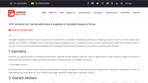
Top Manufacturers & Suppliers of Variable Frequency Drives
Website: darwinmotion.com
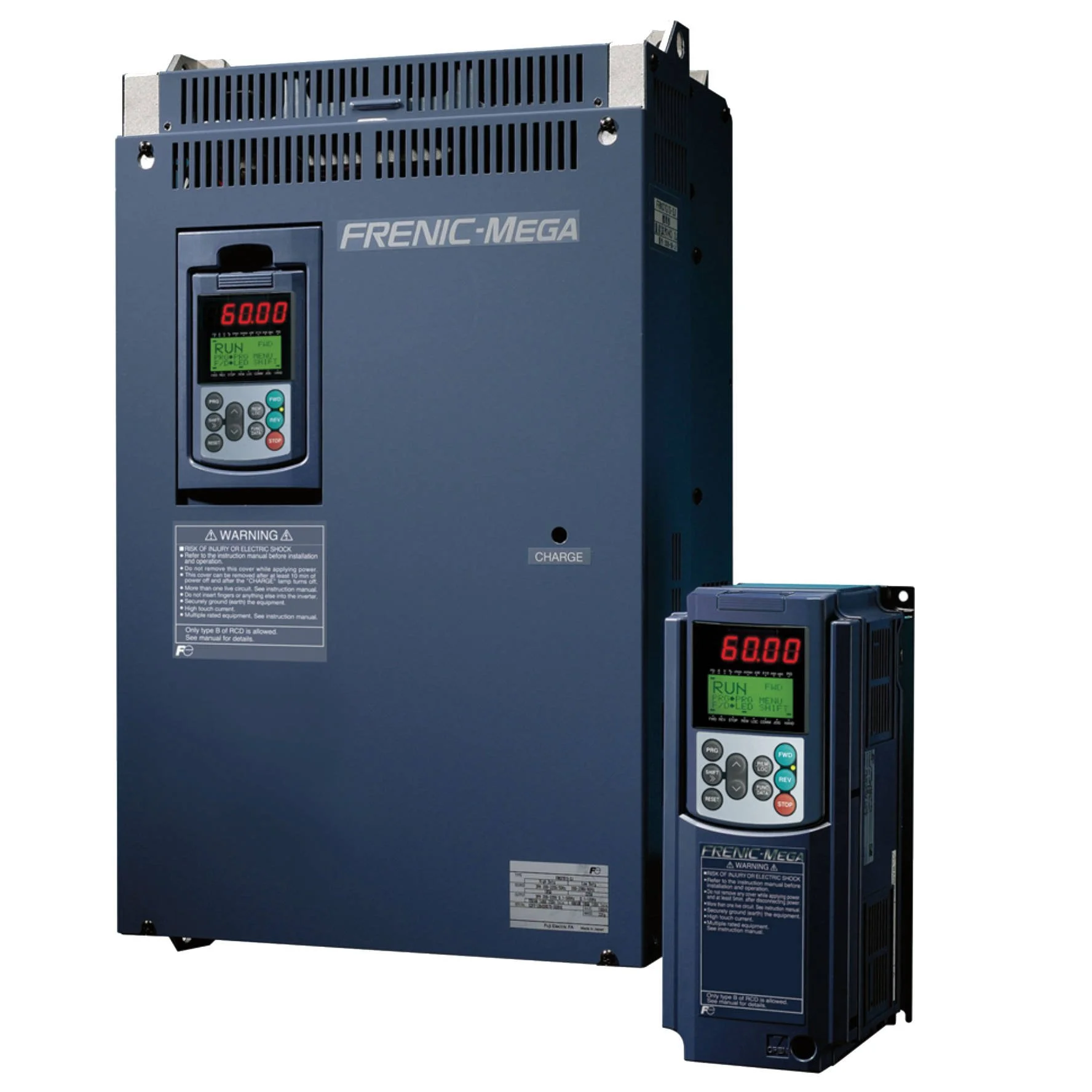
Siemens: Sinamics series VFDs for simple pumps to complex machinery, emphasizing efficiency and versatility. Schneider Electric: Altivar series with energy savings, high performance, and easy-to-use interface for HVAC to manufacturing applications. Darwin Motion: Matrix-900, Matrix 350, Matrix 500, Matrix 680, and Matrix 880 series covering low, medium, and high voltage applications, designed for …

Analysis of the Top 25 Variable Frequency Drive (VFD) Companies …
Website: finance.yahoo.com
No product details found in the provided text. The content appears to be a Yahoo error page (‘Oops, something went wrong’) containing only navigation menus and site structure elements, with no actual article content about Variable Frequency Drives, solar inverters, or industrial automation.
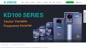
Best Variable Frequency Drive Brands Manufacturers and Suppliers …
Website: thefrequencyinverters.com
SHENZHEN K-EASY AUTOMATION CO., LTD. (K-DRIVE) manufactures Variable Frequency Drives (VFDs) and industrial automation equipment. Key product series include: KD600E (elevator/lift frequency inverter), KD100 Series (mini vector frequency inverter), KD700 Series (book type high-performance vector inverter), KD600M (high-performance vector inverter), KD600 Series (general vector inverter), and KD600/…

26 Leading Variable Frequency Drive Companies Shaping the …
Website: researchandmarkets.com
The global Variable Frequency Drive (VFD) market is projected to expand from USD 24.03 billion (2024) to USD 31.01 billion by 2030, driven by digital transformation and sustainability imperatives. Key product innovations across leading manufacturers include advanced digital integration with Industrial IoT platforms (ABB, Rockwell Automation Connected Enterprise, Schneider Electric EcoStruxure) ena…
B2B Engineering FAQs About Variable Frequency Drive Induction Motor
-
How do I properly size a VFD for an induction motor subject to high inrush currents or heavy starting torque?
When sizing a VFD for applications with high starting inertia—such as screw conveyors, crushers, or deep-well pumps—it is critical to account for inrush current beyond the motor’s nameplate FLA (Full Load Amps). Industry best practice, particularly for volumetric feeding or high-torque startup conditions, recommends selecting a VFD with a current rating of at least 2 times the motor’s full-load amps. This ensures sufficient overload capacity (typically 150% for 60 seconds) to handle mechanical shock without tripping. Additionally, verify the VFD’s I²t curve matches the motor’s thermal characteristics, and consider upgrading by one power size if operating in ambient temperatures exceeding 40°C or altitudes above 1,000 meters. -
What is the quantitative energy-saving potential when using a VFD with an induction motor on centrifugal pumps versus traditional throttling methods?
The energy savings follow the Affinity Laws: power consumption is proportional to the cube of the speed (P ∝ N³). Reducing motor speed by just 20% can decrease power consumption by approximately 50% in variable torque applications such as HVAC, irrigation, or water treatment pumps. Unlike mechanical throttling—which forces the motor to run at full speed while restricting flow (wasting energy as heat and pressure loss)—a VFD modulates frequency and voltage to match actual hydraulic demand. For a 75 kW irrigation pump operating at 80% flow for 6,000 hours annually, this translates to roughly 30–35% reduction in kWh consumption and significant demand charge avoidance. -
What are the critical configuration parameters when operating an induction motor via VFD using DC input from solar PV arrays (solar pumping)?
Solar pump inverters must manage the non-linear output of PV arrays through Maximum Power Point Tracking (MPPT) algorithms to maintain optimal DC bus voltage (typically 400V–800V DC for three-phase systems). Critical parameters include: (1) V/f curve optimization to prevent magnetic saturation at low frequencies; (2) Low Voltage Ride-Through (LVRT) settings to avoid nuisance trips during cloud transients; and (3) Soft-start ramp times (typically 3–10 seconds) to limit inrush current drawn from the PV array. Ensure the VFD supports wide DC input voltage ranges and includes dry-run protection for borehole pumps. -
How do long cable runs between the VFD and induction motor affect system reliability, and what mitigation measures are required?
Cable lengths exceeding 50 meters (or 30 meters for VFDs with high switching frequencies >6 kHz) can create voltage reflection due to impedance mismatch, generating standing waves that stress motor insulation (potentially reaching 2–3x DC bus voltage). To mitigate this: (1) Install dV/dt filters or sinusoidal output filters at the VFD terminals; (2) Use inverter-duty motors with reinforced insulation (Class F or H); and (3) Maintain shielded, symmetrical motor cables with proper grounding at both ends to reduce EMI. For agricultural solar pumping installations where motor leads may exceed 100 meters, specify reactors or filtered VFDs to prevent bearing currents and premature winding failure. -
In which applications should I specify sensorless vector control (SVC) over standard V/f control for induction motors?
Select sensorless vector control when your application requires: (1) High starting torque (>150% rated torque at 0.5 Hz) for extruders or positive-displacement pumps; (2) Precise speed regulation (±0.5% accuracy) despite load variations; or (3) Rapid dynamic response for indexing conveyors or machine tools. Standard V/f control is sufficient for variable torque loads (centrifugal pumps/fans) where precise torque control is unnecessary. SVC algorithms automatically compensate for slip and rotor resistance changes, maintaining constant flux—critical for maintaining flow rates in multi-pump solar irrigation systems subject to varying insolation. -
What harmonic distortion considerations should EPC contractors address when integrating VFDs into existing plant electrical distribution systems?
VFDs introduce current harmonics (typically 5th, 7th, 11th) that can cause transformer overheating and neutral conductor overloading. For industrial installations, specify: (1) Line reactors (3% impedance) or DC link chokes to reduce THDi (Total Harmonic Current Distortion) to <35%; (2) Active Front End (AFE) drives for sensitive grids or compliance with IEEE 519 / G5/4 standards; and (3) Isolation transformers for multiple VFD installations to prevent harmonic resonance. In solar pumping projects, ensure the VFD’s EMC filter meets Class A or B emission standards to prevent interference with SCADA communication lines. -
What environmental protection and thermal management specifications are essential for VFDs in outdoor agricultural or desert solar pumping applications?
Outdoor installations require IP65 or IP66 enclosures to protect against dust ingress and high-pressure water jets. Critical thermal considerations include: (1) Derating curves—reduce output current by 2–3% per °C above 40°C ambient; (2) Conformal coating on PCBs to resist humidity and corrosive gases (H₂S in agricultural settings); and (3) Passive cooling (heatsink) designs with vertical mounting orientation to maximize natural convection. For desert environments, specify VFDs with wide operating temperature ranges (-20°C to +60°C) and automatic fan control to minimize sand infiltration into cooling channels. -
How do I calculate braking resistor requirements for high-inertia induction motor loads to prevent DC bus overvoltage faults?
For high-inertia loads (large flywheels, centrifuges, or downhill conveyors), calculate braking energy using: E = ½J(ω₁² – ω₂²), where J is moment of inertia and ω is angular velocity. Select a braking resistor with wattage based on the duty cycle (typically 10–20% ED for cyclic applications) and resistance value determined by: R = V_DC² / P_brake, where V_DC is the bus voltage (typically 780V for 400V AC systems). Ensure the VFD’s internal braking chopper duty cycle exceeds your calculated deceleration frequency. For continuous regenerative applications (crane hoists), consider active front-end or regenerative braking units instead of dissipative resistors.
Disclaimer
⚠️ Important Disclaimer
The information provided in this guide is for educational purposes. Industrial applications and electrical engineering projects carry inherent risks. B2B buyers and contractors must conduct thorough technical due diligence and verify regional compliance before installation or procurement.
Conclusion: Partnering with Boray Inverter for Variable Frequency Drive Induction Motor
Implementing variable frequency drive technology with induction motors represents a strategic imperative for modern industrial and agricultural operations seeking to optimize energy efficiency and process control. By leveraging the affinity laws for variable torque applications—where a 20% reduction in motor speed can yield nearly 50% energy savings—and enabling precise speed regulation across diverse load profiles, VFDs eliminate the inefficiencies inherent in fixed-speed operation. Beyond energy conservation, these systems significantly extend motor lifespan through reduced mechanical stress, controlled acceleration profiles, and elimination of high inrush currents that plague direct-on-line starting methods.
However, realizing these full technical and economic benefits requires partnering with a manufacturer that combines deep engineering expertise with rigorous quality assurance. Shenzhen Boray Technology Co., Ltd. stands at the forefront of motor control innovation, specializing in Solar Pumping Inverters and advanced VFD solutions engineered for demanding global applications. With an R&D team comprising 50% of its workforce, Boray Inverter has mastered both Permanent Magnet Synchronous Motor (PMSM) and Induction Motor (IM) vector control technologies, ensuring optimal torque response and efficiency across agricultural irrigation, water treatment, and industrial automation sectors.
Operating two state-of-the-art production lines with 100% full-load testing protocols, Boray guarantees that every variable frequency drive meets stringent international standards for reliability and field durability. Whether you are an EPC contractor designing megawatt-scale solar pumping stations or an automation distributor seeking high-performance motor control solutions, Boray delivers customized VFD configurations tailored to your specific voltage, power, and environmental requirements.
Contact Boray Inverter today at borayinverter.com to discuss your project specifications and request competitive wholesale quotations. Experience how our Chinese manufacturing excellence and advanced vector control innovation can drive your next automation or renewable energy initiative forward.