Item
Description | Description |
| Output | Output voltage | 0V to the input voltage |
| Output frequency | Low – frequency mode : 0.00Hz to 500.00Hz
High – frequency mode : 0.0Hz to 3200.0Hz |
| Carrier frequency | 0.8khz to 16.0khz (automatic adjustment according to the load) |
| Overload capacity | 150% / 1 min |
| Input | Voltage/Frequency | 3-phase: 380V; 50/60Hz
1-phase: 220V; 50/60Hz |
the fluctuation of
voltage | 3-phase: 380V AC ±15%, allowable range: 323V AC to 437V AC
1-phase: 220V AC ±15%, allowable range: 187V AC to 253V AC |
| Frequency range | G type: 110% for long-term, 120% for 22 min, 150% for 1min
P type: 105% for long-term, 120% for 8 min, 150% for 1min |
Control
Character | Frequency Setting
Resolution | Analog Input | 0.025% of maximum output frequency |
| Digital Setting | 0.01 Hz |
| Control mode | Voltage/Frequency (V/F) control, Sensorless vector control (SVC) and Feedback vector control (FVC) |
| Startup torque | SVC | 0.25 Hz/150% |
| FVC | 0 Hz/180% |
| Speed range | SVC | 1: 200 |
| FVC | 1: 1000 |
Speed stability
accuracy | SVC | ±0.5% (SVC) |
| FVC | ±0.02% (FVC) |
| Torque boost | Customized boost 0.0 % to 30.0 % |
| V/F curve | Straight-line V/F curve, Multi-point V/F curve, Complete V/F separation
and Half V/F separation |
| Wave current limit | In V/F mode, to achieve fast response and ensure the normal operation of
the inverter |
| Ramp mode | Straight-line ramp, S-curve ramp
Four separate acceleration/deceleration time: 0.1s to 6500s |
Automatic voltage
regulation (AVR) | The system maintains a constant output voltage automatically when the
grid voltage changes through the permissible range |
| DC injection braking | DC injection braking frequency: 0 Hz to max frequency
DC injection braking active time: 0.0s to 100.0s
Current level of DC injection braking: 0% to 100% |
| Jog running | Frequency range of jog running: 0.00 to max frequency
Acceleration/Deceleration time of jog running:0.0s to 6500.0s |
Onboard multiple
preset speeds | The system implements up to 16 speeds by using simple PLC function or by
using digital input signals |
Overvoltage and
overcurrent stall
control | Overvoltage and overcurrent stall control |
Torque limit and
control | The system limits the torque automatically.
Torque control is applied in vector control. |
Undervoltage
Restrain during
Running | Specially for users with a low or unsteady voltage power grid: even lower
than the allowable voltage range, the system can maintain the longest
possible operating time based on its unique algorithm and residual energy
allocation strategy |
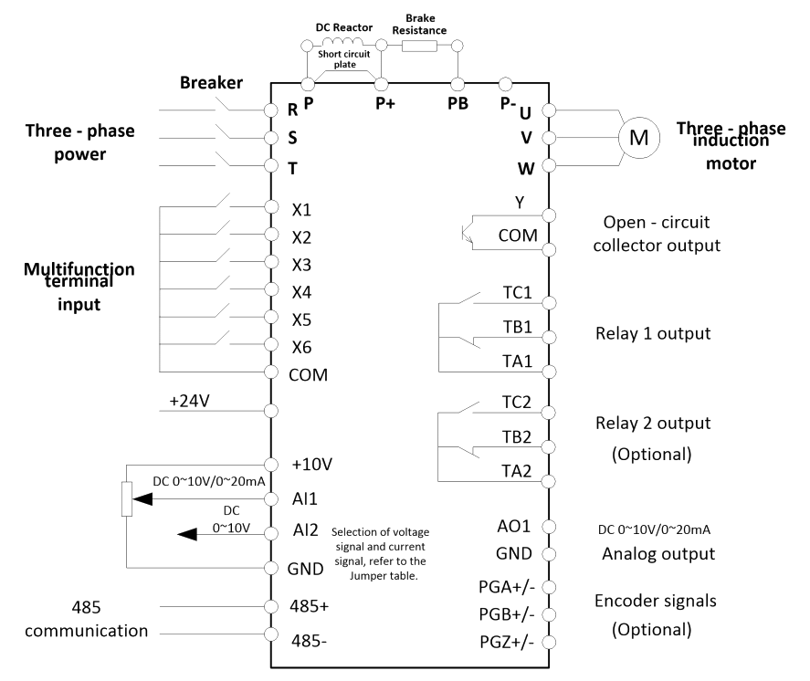
Control input
and output
signals | Command source | Allows different methods of switching between command sources:
Operating panel (keypad & display), Terminal I/O control and Serial
communication |
Main frequency
reference setting
channel | Allows different methods of switching between frequency reference
setting channels: Digital setting, Analog voltage reference, Analog current
reference, Pulse reference(Optional), Communication reference |
Auxiliary frequency
reference setting
channel | Allows fine tuning of the auxiliary frequency and main & auxiliary
calculation |
| Input terminals | 0 to 5V keyboard potentiometer input
Six digital input (X) terminals, one of which supports up to 50 kHz
high-speed pulse inputs(Optional).
Two analog input (AI) terminals, one of which supports only 0 to10 V input,
and the other supports 0 to 10 V and 4 to 20 mA current input |
| Output terminals | Single open-collector output terminal (high-speed pulse (Optional)) for a
square-wave signal
Single relay output terminal
Single extra AO terminal |
serial
communication
interface | RS-485 interface |
| Protective Function | Overcurrent, overvoltage, undervoltage, module fault, electric thermal
relay, overheat, short circuit, default phase of input and output, motor
parameter adjustment abnormality, internal memory fault, etc. |
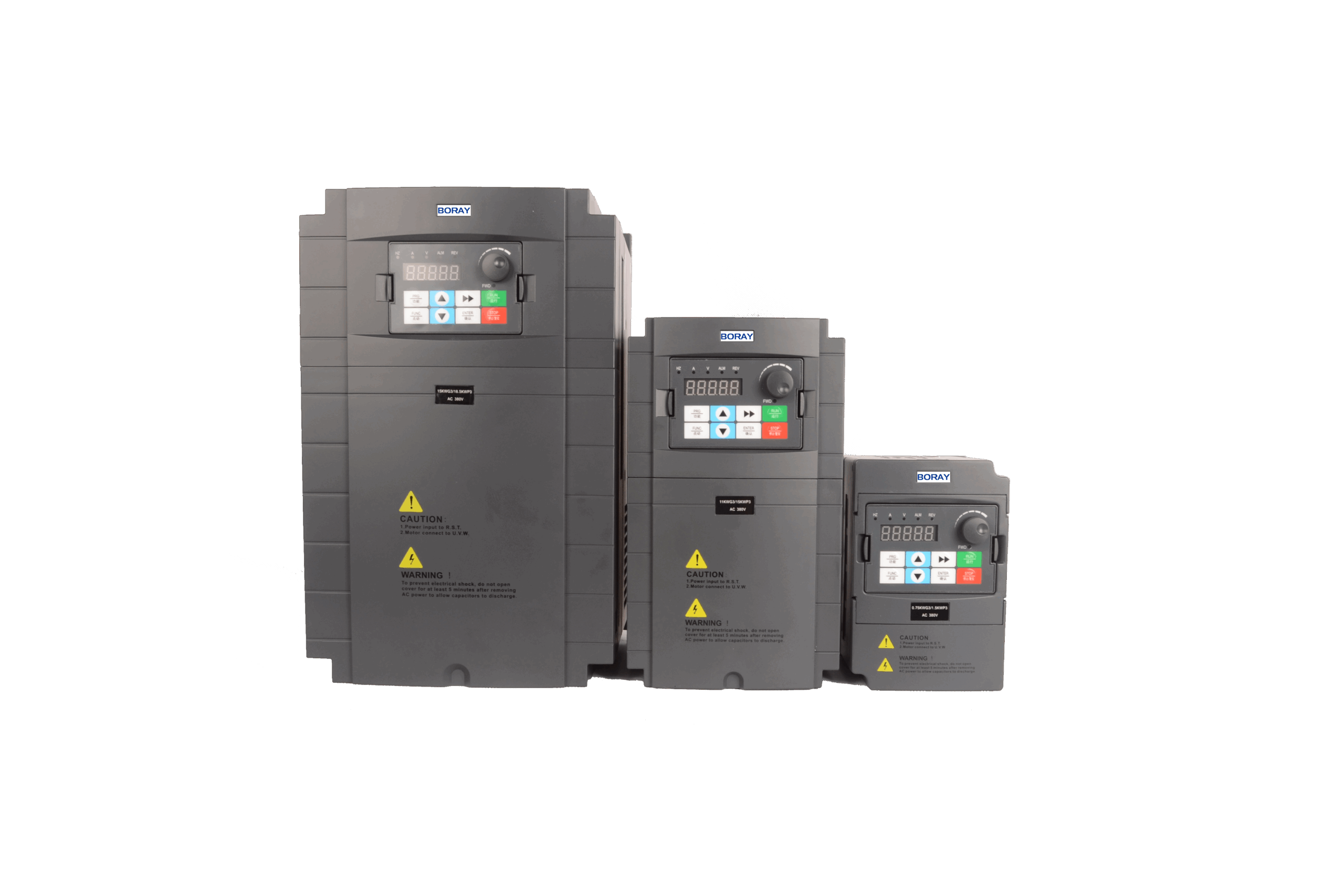
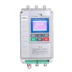
| Display | Five digit digital
display (LED) and
Status indicator light | Parameter setting:
Display parameter number and value. | Function code, Data, status |
Running state display:
Display operation frequency, current, etc. |
| Fault display: Display the fault code. |
| Environment | Installation location | Install the inverter where it is indoors and protected from direct sunlight,
dust and corrosive or combustible gases. Running in derated capacity
above 1000m. |
Ambient
Temperature | -10°C to +40°C (please run the VFD in derated capacity when ambient
temperature is 40°C to 50°C) |
| Ambient Humidity | 20% to 95%RH, without condensing drops |
Operation
temperature | –10°C to +50°C |
| Vibration | Less than 0.5 g |
| Storage temperature | –25°C to +65°C |
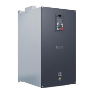
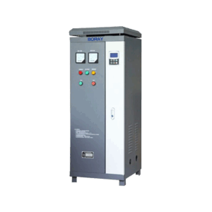
| Installation Method | Wall-hanging type, cabinet type |
| Structure | Protection Level | IP20 |
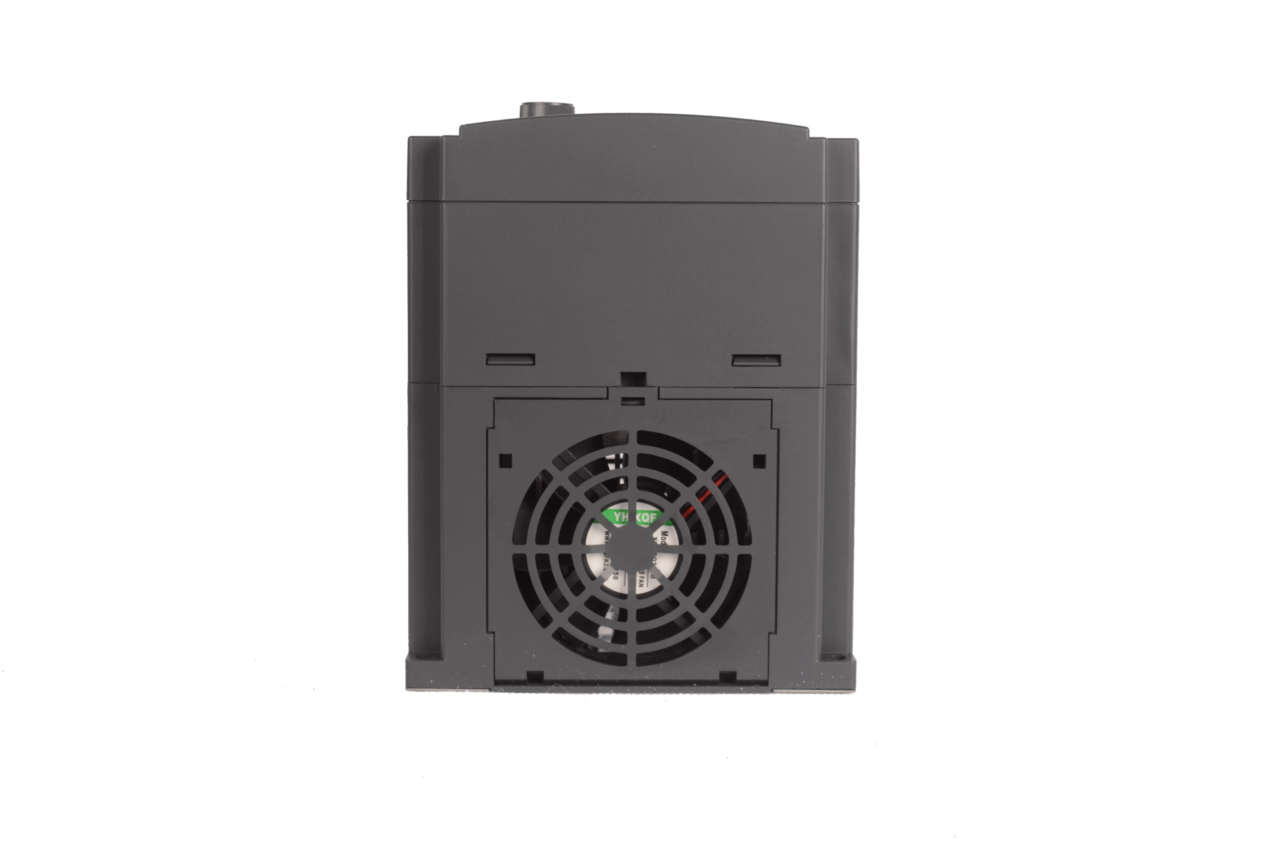
| Cooling Method | Air cooling with fan control |