Every year, industrial facilities waste thousands in electricity running motors at fixed speeds—whether the load demands full power or not. If you’re managing pumps, conveyors, or HVAC systems, that inefficiency directly erodes your margins and shortens equipment life.
Understanding how a Variable Frequency Drive (VFD) actually works isn’t just academic curiosity—it’s the key to matching motor output to real-time demand, slashing energy costs by up to 50%, and eliminating the mechanical stress that causes premature bearing failure. For agricultural operations balancing tight irrigation budgets or EPC contractors specifying reliable motor control, mastering VFD fundamentals transforms capital equipment from a fixed cost into a strategic efficiency tool.
How Does a Variable Frequency Drive Work?
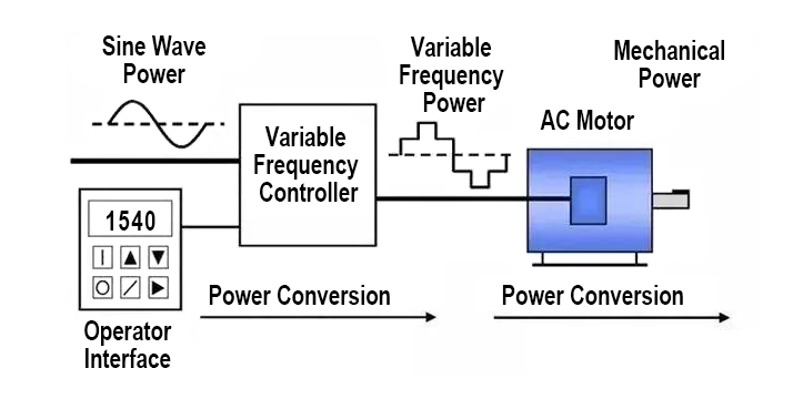
A Variable Frequency Drive (VFD) is an electronic power conversion device that controls the rotational speed, torque, and direction of an AC induction motor or permanent magnet synchronous motor (PMSM) by varying the frequency and voltage of the electrical power supplied to the motor.
The Three-Stage Power Conversion Process
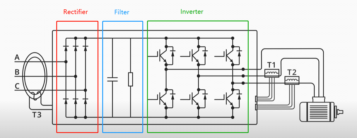
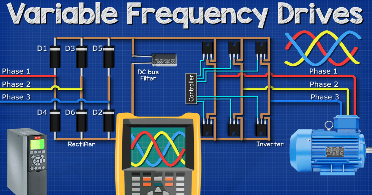
1. Rectification (AC to DC Conversion)
The VFD first converts incoming fixed-frequency AC power (typically 50Hz or 60Hz) into DC power using a rectifier bridge. In standard low-voltage VFDs (below 1000V), this consists of six diodes arranged in a three-phase bridge configuration. As the AC sine wave alternates, diodes conduct when their phase voltage exceeds the others, creating six current pulses per cycle—known as a “six-pulse” rectifier. This produces a DC voltage with an AC ripple component (approximately 580V–680V on a 480V system).
2. DC Bus Filtering (Energy Storage)
The pulsating DC voltage passes through the DC link (or DC bus), which contains capacitors and sometimes inductors. These components act as energy reservoirs, absorbing the AC ripple and delivering smooth, stable DC voltage (typically around 650V for 480V input systems). The capacitance value determines the drive’s ability to handle voltage fluctuations and provide ride-through capability during brief power interruptions.
3. Inversion (DC to Variable AC)
The inverter section converts the stable DC back into variable-frequency AC using Insulated-Gate Bipolar Transistors (IGBTs) or Silicon Carbide (SiC) MOSFETs. Through Pulse Width Modulation (PWM), these semiconductor switches turn on and off at high frequencies (typically 2–16 kHz) to simulate a sinusoidal waveform. By varying the pulse width and switching pattern, the VFD generates AC output at any frequency from 0 Hz to several hundred Hz, while simultaneously adjusting the voltage to maintain the critical Volts-per-Hertz (V/Hz) ratio.
Motor Speed Control Fundamentals
The synchronous speed of an AC motor follows the formula:
Ns = (120 × f) / P
Where:
– Ns = Synchronous speed (RPM)
– f = Frequency (Hz)
– P = Number of motor poles
For a 4-pole motor operating on 60 Hz mains, the synchronous speed calculates to 1,800 RPM. By reducing the VFD output to 30 Hz while proportionally reducing voltage to maintain the V/Hz ratio (typically 7.67 V/Hz for 460V/60Hz systems), the motor speed drops to 900 RPM while maintaining rated torque capability.
Technical Factors Affecting VFD Selection and Cost
Power Rating and Voltage Configuration
VFD costs scale exponentially with power rating. Units range from fractional horsepower (0.5 kW) to megawatt-class systems. Three-phase 380V–480V industrial drives offer better cost-per-kW economics than single-phase 220V units due to reduced current requirements and simpler power stages. Single-phase input drives require derating (typically 50% of three-phase rating) and additional input capacitance, increasing cost per kilowatt.
Control Methodology Complexity
- V/Hz Scalar Control: Basic open-loop control maintaining constant flux; cost-effective for pumps and fans but limited low-speed torque.
- Sensorless Vector Control: Uses motor current feedback to estimate rotor position; provides 150%–200% starting torque at 0.5 Hz without encoder feedback. Adds 15%–25% cost over scalar drives.
- Closed-Loop Vector Control: Requires encoder/ resolver feedback for precise speed and torque control (±0.01% speed accuracy); essential for crane, hoist, and positioning applications. Increases system cost by 30%–40%.
- Direct Torque Control (DTC): Advanced algorithm controlling motor flux and torque directly; fastest dynamic response but requires sophisticated processing hardware.
Environmental Protection and Thermal Management
IP20 (open chassis) drives suit clean electrical rooms and offer lowest cost. IP54/NEMA 12 enclosures add 20%–35% cost for dust protection, while IP66/NEMA 4X stainless steel enclosures for washdown environments can double the base drive cost. High-temperature ratings (50°C ambient vs. standard 40°C) require larger heat sinks and derating, affecting pricing.
Harmonic Mitigation Requirements
Standard six-pulse drives generate 5th, 7th, and 11th harmonic currents. For compliance with IEEE 519 or local utility standards, specify:
– DC Link Chokes: Cost-effective harmonic reduction (3%–5% impedance); adds 5%–8% to drive cost.
– Active Front End (AFE): Regenerative four-quadrant operation with 250 kW) requiring minimal harmonics; significantly increases transformer and drive costs.
Communication and I/O Capabilities
Basic keypad control costs least, while integrated PLC functionality, Ethernet/IP, Modbus TCP, or PROFINET communication cards add 10%–15%. Safe Torque Off (STO) safety circuits per IEC 61800-5-2 add 8%–12% but eliminate external contactors.
Industrial Sizing and Sourcing Best Practices
Right-Sizing vs. Over-Sizing
Avoid the common error of oversizing VFDs by 30%–50% “for safety.” Modern VFDs provide 150% overload capacity for 60 seconds. Oversizing reduces power factor, increases harmonic distortion, and wastes capital. Size the VFD to the motor’s full-load current (FLA) with 10%–15% margin for voltage imbalance or temperature derating.
Load Profile Analysis
- Variable Torque Loads (centrifugal pumps, fans): Follow the cube law—50% speed reduction yields 87.5% energy savings. Standard V/Hz drives suffice.
- Constant Torque Loads (conveyors, compressors): Require full torque at low speeds; specify vector control with 150% overload capacity and forced ventilation or external cooling.
- High Inertia Loads (centrifuges, flywheels): Calculate deceleration torque requirements. If regeneration exceeds 20% of duty cycle, specify dynamic braking resistors or regenerative drives to prevent DC bus overvoltage faults.
Related Technical Insight
Input Power Quality Considerations
Install input line reactors (3% impedance) when:
– Supply transformer kVA exceeds drive kVA by more than 20:1
– Power factor correction capacitors exist on the same bus
– Voltage unbalance exceeds 2%
– Multiple drives share a common bus
This protects against nuisance tripping and extends DC bus capacitor life by 30%–50%.
Cable and Motor Compatibility
For cable runs exceeding 50 meters (164 feet) between VFD and motor, specify output reactors or dV/dt filters to prevent reflected wave phenomena that damage motor insulation. Inverter-duty motors (NEMA MG1 Part 31) with enhanced insulation (1600V rise-time withstand) prevent premature failure when retrofitting existing motors.
Why Source Inverters and VFDs from China?
China has emerged as the global center for power electronics manufacturing, hosting over 60% of worldwide VFD production capacity. Sourcing directly from established Chinese manufacturers offers distinct competitive advantages:
Advanced R&D Integration: Leading Chinese factories maintain vertical integration from semiconductor packaging to final assembly, enabling rapid adoption of Silicon Carbide (SiC) and Gallium Nitride (GaN) technologies that improve efficiency by 2%–4% over traditional IGBT drives.
Cost-Effective Manufacturing: Direct factory access eliminates distributor markups (typically 25%–40% in Western markets) while maintaining IEC 61800 quality standards. Chinese manufacturers offer MOQ flexibility for OEMs, supporting everything from prototype batches to high-volume production.
Customization Agility: Domestic engineering teams provide rapid firmware customization for specific applications—whether agricultural pump control algorithms, solar pumping MPPT integration, or specialized communication protocols—without the 12–16 week lead times common with European brands.
Supply Chain Resilience: Proximity to raw materials (copper, rare earth magnets, semiconductors) and component ecosystems ensures stable pricing and 4–6 week delivery schedules even during global shortages.
Boray Inverter: Your Strategic OEM/ODM Partner
When evaluating Chinese VFD manufacturing partners, engineering capability and quality assurance differentiate commodity suppliers from strategic allies. Boray Inverter (borayinverter.com) represents the new generation of technology-driven Chinese manufacturers.
With 50% of our workforce dedicated to R&D engineering, Boray maintains deep expertise in both Induction Motor (IM) vector control and Permanent Magnet Synchronous Motor (PMSM) control algorithms. Our engineering team has developed proprietary sensorless vector control achieving 200% starting torque at 0.5 Hz—performance metrics matching premium European brands at significantly lower cost points.
Our manufacturing facility features two modern automated production lines with 100% full-load testing protocols. Every VFD undergoes burn-in testing at rated current and temperature before shipment, ensuring 99% tracking efficiency.
For OEMs and system integrators, Boray provides white-label manufacturing, custom firmware development, and application-specific hardware modifications. Whether you require specialized vector control for crane applications, integrated PLC functionality, or solar pumping solutions with remote monitoring capabilities, our engineering team delivers production-ready solutions within 3–4 weeks.
Contact Boray Inverter today to discuss wholesale pricing, technical specifications, and custom VFD solutions tailored to your specific motor control requirements.
Frequently Asked Questions (FAQs)
What is the difference between a VFD and a soft starter?
A soft starter temporarily reduces voltage during motor starting to limit inrush current (typically 3–5 times FLA), but runs the motor at fixed line frequency once started. A VFD provides full variable speed control throughout the operating range, maintains constant V/Hz ratio for optimal flux, and enables energy recovery during deceleration. Soft starters cost 30%–50% less than VFDs but offer none of the operational flexibility or energy savings of variable speed operation.
Can I use a standard motor with a VFD, or do I need an inverter-duty motor?
Standard NEMA Design B motors function with VFDs for speeds above 30 Hz and cable runs under 15 meters. However, for continuous operation below 30 Hz (where cooling fans are ineffective) or cable lengths exceeding 50 meters, specify inverter-duty motors with Class F or H insulation and 1600V surge withstand capability. The additional motor cost (15%–20% premium) prevents insulation failure from PWM voltage spikes and ensures bearing current protection.
How do I calculate energy savings for a pump or fan application?
Centrifugal loads follow the affinity laws: Power varies with the cube of speed. A pump operating at 80% speed consumes (0.8)³ = 51.2% of full-load power. Calculate annual savings using: kW_saved = (Motor_HP × 0.746 × Operating_Hours × Cost_per_kWh) × (1 – (New_Speed/Full_Speed)³). Typical ROI for VFD retrofits on variable-load pumps ranges from 8 to 18 months depending on duty cycle and local electricity rates.
Why does my VFD show overvoltage faults during deceleration?
Overvoltage trips (typically >750V DC on 480V systems) occur when the motor acts as a generator during rapid deceleration, pumping energy back into the DC bus faster than the capacitors can absorb or the braking chopper can dissipate. Solutions include: extending deceleration ramp time, installing dynamic braking resistors (sized to 10%–20% of drive kW rating), or upgrading to regenerative drives that return energy to the line rather than dissipating it as heat.
What control method should I specify for a conveyor with high starting torque?
Specify sensorless vector control (also called open-loop vector) as the minimum requirement. This method estimates motor flux and torque current separately, providing 150%–200% starting torque at 0.5 Hz without requiring encoder feedback. For precise speed holding (±0.1%) or zero-speed holding capability, upgrade to closed-loop vector control with encoder feedback. Avoid basic V/Hz control for high-friction starts, as it provides only 100%–120% starting torque and may stall the motor.