Introduction: Sourcing Variable Frequency Drive Speed Control for Industrial Use
In an era where operational efficiency and sustainability dictate competitive advantage, variable frequency drive (VFD) speed control has emerged as the cornerstone of modern motor management. Whether optimizing irrigation systems in remote agricultural installations or fine-tuning conveyor networks in heavy manufacturing, the ability to precisely modulate motor speed and torque translates directly into measurable energy savings—often reducing consumption by 40% to 80% compared to direct-on-line operation. For EPC contractors and automation distributors sourcing equipment for demanding environments, selecting the right VFD technology is no longer merely an electrical decision; it is a strategic investment in system longevity and process optimization.
This comprehensive guide addresses the critical specifications and sourcing considerations that industrial engineers and project managers must navigate when implementing VFD speed control solutions. We examine the distinct architectures of solar pump inverters for off-grid water management, heavy-duty industrial drives for constant torque applications, and specialized agricultural VFDs engineered for harsh environmental conditions. Beyond basic frequency modulation, we explore essential technical parameters—including harmonic mitigation strategies, IP enclosure ratings for dust and moisture protection, and integration protocols with PLC and SCADA systems—that determine real-world performance in the field.
From evaluating manufacturer capabilities and global certification standards (CE, UL, IEC) to understanding the total cost of ownership across solar pumping and industrial automation projects, this resource provides the technical depth required to specify drives that deliver reliable speed control while maximizing ROI in diverse operational contexts.
Article Navigation
- Top 3 Variable Frequency Drive Speed Control Manufacturers & Suppliers List
- Introduction: Sourcing Variable Frequency Drive Speed Control for Industrial Use
- Technical Types and Variations of Variable Frequency Drive Speed Control
- Key Industrial Applications for Variable Frequency Drive Speed Control
- Top 3 Engineering Pain Points for Variable Frequency Drive Speed Control
- Component and Hardware Analysis for Variable Frequency Drive Speed Control
- Manufacturing Standards and Testing QC for Variable Frequency Drive Speed Control
- Step-by-Step Engineering Sizing Checklist for Variable Frequency Drive Speed Control
- Wholesale Cost and Energy ROI Analysis for Variable Frequency Drive Speed Control
- Alternatives Comparison: Is Variable Frequency Drive Speed Control the Best Choice?
- Core Technical Specifications and Control Terms for Variable Frequency Drive Speed Control
- Future Trends in the Variable Frequency Drive Speed Control Sector
- B2B Engineering FAQs About Variable Frequency Drive Speed Control
- Disclaimer
- Conclusion: Partnering with Boray Inverter for Variable Frequency Drive Speed Control
Technical Types and Variations of Variable Frequency Drive Speed Control
Selecting the optimal VFD topology requires careful analysis of your power infrastructure, motor specifications, and load dynamics. While all variable frequency drives regulate motor speed through PWM control, distinct architectural variations exist to address specific technical constraints—from rural single-phase agricultural sites to high-inertia industrial regenerative applications. Below is a technical breakdown of the primary VFD classifications relevant to solar pumping, industrial automation, and motor control projects.
| Type | Technical Features | Best for (Industry) | Pros & Cons |
|---|---|---|---|
| Solar DC-to-AC VFDs (PV Pump Inverters) | Wide DC input voltage range (200V–800VDC), MPPT algorithms (99% tracking efficiency), IP65/66 ingress protection, V/Hz or open-loop vector control, automatic grid/solar switching (hybrid mode), dry-run and water level protection | Agriculture irrigation, remote water supply, livestock watering, off-grid desalination | Pros: Eliminates grid dependency; maximizes PV array yield; replaces diesel generators; reduces CO₂ footprint Cons: Weather-dependent output; requires PV array capital expenditure; needs water storage or hybrid backup for consistent operation |
| Three-Phase AC Input VFDs (Standard Industrial) | 380V–480V (or 690V) 3-phase input, diode bridge rectifier, IGBT inverter topology, 0–400Hz output range, built-in Class A EMC filters, Modbus/Profibus/EtherNet/IP communication, 150% overload for 60s | Manufacturing lines, HVAC systems, water treatment plants, mining conveyors, general industrial automation | Pros: Cost-effective per kW; robust for continuous duty; wide power range (0.4kW–MW+); extensive diagnostic capabilities Cons: Requires three-phase infrastructure; generates heat during braking (requires braking resistors); fixed power factor (~0.95 lagging) |
| Single-Phase Input VFDs (Phase Conversion Drives) | 220V–240V single-phase input, synthesized three-phase 220V output, voltage doubler circuit on DC bus, derated capacity (typically 50% of three-phase rating), compact form factor (IP20/IP54) | Rural agricultural pumps, small workshops, residential pressure systems, retrofitting legacy single-phase sites | Pros: Enables three-phase motor operation where only single-phase exists; lower infrastructure cost than utility three-phase installation Cons: Limited to ~2.2kW (3HP) practical maximum; higher input current draw; potential capacitor ripple issues; not suitable for continuous heavy loads |
| Regenerative VFDs (Active Front End – AFE) | IGBT-based active rectifier (regenerative bridge), four-quadrant operation (motoring/regenerating), <5% THDi (total harmonic current distortion), unity power factor (0.99+), shared DC bus capability, LCL filter integration | Cranes and hoists, centrifuges, downhill conveyors, dynamometer test stands, high-inertia machine tools | Pros: Returns braking energy to grid (30–40% energy recovery in cyclic apps); eliminates braking resistor heat; IEEE 519/IEC 61000 compliance; reduced cooling requirements Cons: 20–40% cost premium over standard drives; requires line reactors or LCL filters; complex commissioning; sensitive to grid voltage imbalances |
Solar DC-to-AC VFDs (Photovoltaic Pump Inverters)
These specialized drives are engineered specifically for photovoltaic water pumping systems, representing a distinct category from standard grid-tied VFDs. Unlike conventional drives that require stable AC input, solar pump inverters accept variable DC voltage directly from PV arrays (typically 200V–800VDC depending on configuration) and utilize Maximum Power Point Tracking (MPPT) algorithms to maintain the array at its optimal voltage-current curve as solar irradiance fluctuates throughout the day.
For EPC contractors and agricultural project managers, critical specifications include dual-mode operation capability—allowing automatic switching between solar priority and grid backup when irradiance is insufficient—and IP66-rated enclosures that withstand outdoor agricultural environments without additional electrical housing. Advanced models incorporate pump-specific protections such as dry-run detection (using current signature analysis) and water tank level management through floating point inputs. When specifying these systems, engineers must calculate the array-to-motor power ratio (typically 1.3:1 to 1.6:1) to account for variable solar conditions while ensuring the VFD’s DC voltage range matches the open-circuit voltage of the PV string configuration.
Three-Phase AC Input VFDs (Standard Industrial)
The ubiquitous workhorse of industrial automation, these VFDs utilize a six-pulse diode rectifier front-end to convert three-phase AC to DC, which is then inverted using IGBT switching devices to produce variable frequency/voltage output. For industrial engineers, the key differentiator lies in control methodologies: V/Hz control for general-purpose fan and pump applications versus sensorless vector control for high-torque, low-speed operations requiring 150% starting torque at 0.5Hz.
Integration capabilities are paramount for automation distributors—modern units offer embedded EtherNet/IP, Profinet, or Modbus TCP for seamless PLC integration, along with Automatic Device Configuration (ADC) that reduces commissioning time. When deployed in solar hybrid projects, these drives serve as the grid-tied backup system, requiring specification of automatic transfer switches (ATS) and synchronization controls to switch between solar VFD output and grid power without process interruption. Note that standard models require external braking resistors for high-inertia loads, dissipating energy as heat rather than returning it to the source.
Single-Phase Input VFDs (Phase Conversion Drives)
Engineered for rural electrification scenarios where three-phase utility infrastructure is unavailable or cost-prohibitive, these drives accept 220V–240V single-phase input and synthesize three-phase output through a voltage doubler circuit on the DC bus. This topology enables farmers and agricultural contractors to operate standard three-phase submersible pumps and irrigation motors using existing single-phase rural distribution networks.
However, electrical engineers must account for derating requirements: a drive rated for 2.2kW on three-phase input can typically only support a 1.1kW–1.5kW motor when powered by single-phase, due to increased input current (approximately √3 higher per phase) and elevated ripple current on DC bus capacitors
Key Industrial Applications for Variable Frequency Drive Speed Control
Variable frequency drive speed control has evolved from simple motor regulation to a strategic asset for operational efficiency across industrial infrastructures. By modulating motor speed to match real-time load demands rather than maintaining constant full-speed operation, VFDs exploit the cubic relationship between speed and power consumption (affinity laws) to deliver substantial energy arbitrage. Below is a technical breakdown of high-impact deployment scenarios, with specific procurement criteria for EPC contractors and automation engineers.
| Sector | Application | Energy Saving Value | Sourcing Considerations |
|---|---|---|---|
| Agriculture & Irrigation | Solar-Powered Deep Well & Surface Pumping Systems | 60–80% displacement of diesel generator costs; 30–50% reduction in grid electricity consumption for irrigation | IP65/NEMA 4X enclosures for outdoor UV exposure; wide DC input voltage range (200V–800V) for solar array compatibility; integrated MPPT algorithms; anti-islanding protection per IEEE 1547 |
| Water & Wastewater | Municipal Booster Stations & Aeration Basin Blowers | 40–60% reduction in pumping energy via affinity law optimization; 20–30% reduction in aeration power through dissolved oxygen (DO) feedback control | Active harmonic filters (THDi <5%) to protect PLCs; redundant cooling fans for 24/7 operation; Modbus RTU/TCP and Profibus DP integration; NEMA 4X stainless steel chassis for corrosive environments |
| HVAC & Building Automation | Chilled Water Primary/Secondary Loops & Air Handling Units (AHU) | 30–45% total HVAC energy savings; demand-based static pressure reset in VAV systems | BACnet MS/TP or EtherNet-IP protocol support; low acoustic noise emission (<60 dB) for occupied spaces; IEEE 519 compliance for harmonic mitigation; sleep/wake functionality for low-load periods |
| Mining & Cement | Long-Distance Conveyor Belts, Ball Mills, and Primary Crushers | 20–35% energy recovery via regenerative braking on downhill conveyors; elimination of mechanical soft-start couplings; extended bearing life through controlled acceleration | 150% overload capacity for 60 seconds (heavy-duty HD rating); regenerative drive modules (IGBT-based); conformal-coated PCBs for dust/moisture ingress; vibration resistance per IEC 60068-2-6 |
| Manufacturing & Process | Centrifugal Compressors, Extruders, and Precision Spindles | 25–40% process energy optimization; enhanced product quality via ±0.5% speed accuracy and torque control | Closed-loop vector control with encoder feedback; Safe Torque Off (STO) SIL 3/PLe safety integration; EMC compliance (EN 61800-3 Category C2); seamless PLC integration via EtherCAT or Profinet |
Detailed Application Analysis
Agriculture & Irrigation: Solar Pump Inverter Integration
In off-grid and grid-tie agricultural deployments, VFDs function as the power conversion bridge between photovoltaic arrays and AC induction motors or permanent magnet synchronous motors (PMSMs). Unlike conventional pumping systems that rely on diesel generators or grid power with phase balancing issues, solar pump inverters utilize maximum power point tracking (MPPT) to dynamically adjust motor frequency in response to irradiance fluctuations. This eliminates the need for battery storage while maintaining flow rates proportional to solar availability. When sourcing for these applications, prioritize drives with IP65 ingress protection and wide MPP voltage windows to accommodate early morning and late afternoon irradiance without stalling submersible pumps.
Water & Wastewater: Affinity Law Optimization
Municipal pumping stations and aeration systems represent ideal candidates for VFD speed control due to the cubic power relationship with rotational speed. Reducing pump speed by just 20% yields approximately 50% energy savings. Beyond energy efficiency, VFDs mitigate water hammer through controlled ramp-up/down profiles, reducing mechanical stress on pipeline infrastructure. For EPC contractors, specifying drives with integrated harmonic mitigation (active front ends or DC chokes) is critical, as untreated harmonics can disrupt SCADA systems and power quality across the facility.
HVAC & Building Automation: Part-Load Efficiency
Commercial buildings rarely operate at design peak load; VFDs enable variable air volume (VAV) and variable refrigerant flow (VRF) systems to modulate fan and pump speeds based on real-time thermal loads. This part-load optimization, combined with sleep mode functionality during unoccupied hours, delivers rapid ROI in commercial real estate. Procurement teams should verify BACnet compatibility for building management system (BMS) integration and specify drives with automatic energy optimization (AEO) algorithms that minimize magnetization losses at reduced speeds.
Mining & Cement: High-Inertia Load Management
In heavy industrial sectors, VFDs serve dual purposes: energy savings and mechanical protection. For high-inertia applications such as ball mills and conveyor systems, direct-on-line (DOL) starting generates 6–8x inrush current and severe mechanical shock. VFDs provide controlled torque ramping, eliminating clutch wear and belt sag. Regenerative drive configurations are particularly valuable for downhill conveyors, converting gravitational potential energy into reusable power rather than dissipating it as heat in mechanical brakes. Sourcing should focus on heavy-duty overload ratings (150% for 60 seconds) and chassis designs that withstand high particulate environments.
Manufacturing & Process Industries: Precision Torque Control
For process manufacturing requiring exact tension control (paper mills, film extrusion) or precise volumetric flow (chemical dosing), closed-loop vector VFDs provide dynamic torque response independent of motor slip. This level of control prevents material waste and enables synchronized multi-axis operation. Safety-critical applications require drives with integrated Safe Torque Off (STO) circuits to achieve SIL 3/PLe ratings without external contactors, reducing panel complexity and failure points.
Top 3 Engineering Pain Points for Variable Frequency Drive Speed Control
Implementing variable frequency drive speed control in demanding industrial and agricultural environments presents distinct engineering challenges that extend beyond basic motor regulation. While VFDs offer significant energy savings and process optimization, system designers must address specific technical constraints to ensure reliable operation across diverse applications—from solar-powered irrigation in remote locations to precision manufacturing lines.
Scenario 1: Grid Instability and Voltage Fluctuations in Remote Solar Pumping Installations
The Problem: In off-grid agricultural projects and remote industrial sites, VFDs face erratic input voltage from photovoltaic arrays or weak grid infrastructure with significant voltage sags and swells. Traditional drives trip on under-voltage or over-voltage fault codes when solar irradiance fluctuates rapidly due to cloud cover, causing system downtime during critical irrigation windows. Additionally, weak grid connections in rural areas exhibit high impedance, leading to voltage distortion and harmonic resonance that compromise motor control precision and reduce pump efficiency by 15-25%.
The Solution: Deploy solar pump inverters with wide DC voltage input ranges (e.g., 200V-1000V DC) and advanced Maximum Power Point Tracking (MPPT) algorithms that maintain stable motor speed control despite irradiance variations. Specify VFDs with ride-through capabilities (minimum 3-5 seconds) and automatic voltage regulation (AVR) to compensate for ±20% AC grid fluctuations without tripping. Integrated DC chokes and active power factor correction (PFC) circuits minimize harmonic distortion while maintaining constant torque output, ensuring continuous water flow even during partial shading conditions or grid instability.
Scenario 2: Mechanical Stress and Precision Control in High-Inertia Pump Systems
The Problem: Direct-on-line starting creates destructive water hammer, pipeline stress, and NPSH (Net Positive Suction Head) cavitation in centrifugal pumps, while abrupt speed changes induce mechanical fatigue in motor bearings and pump couplings. In precision applications such as chemical dosing or paper machine sections, speed control accuracy below ±0.5% is mandatory to prevent product defects or process variations. Standard VFDs without advanced torque control modes cause pump cavitation at low flow rates (below 30% of BEP—Best Efficiency Point), accelerating impeller erosion and reducing mean time between failures (MTBF) by up to 40%.
TheSolution: Implement VFDs featuring sensorless vector control or direct torque control (DTC) architectures for precise speed regulation across 1:100 speed ranges without encoder feedback. Utilize programmable S-curve acceleration/deceleration profiles (0.1-3600 seconds adjustable) to eliminate hydraulic shock during pump startup. For critical pump applications, select drives with built-in cavitation detection algorithms that automatically adjust operating frequency to maintain minimum suction pressure, and multi-pump cascade control logic for staged operation. Advanced VFDs offer skip-frequency bands to avoid mechanical resonance points, extending mechanical seal life while maintaining ±0.1% speed accuracy under varying load conditions.
Scenario 3: Environmental Exposure and Thermal Management in Harsh Operating Conditions
The Problem: Outdoor agricultural installations expose VFDs to dust ingress, humidity, and temperature extremes (often exceeding 50°C in solar pump enclosures), while industrial environments present chemical vapors and conductive dust that compromise standard IP20-rated electronics. High ambient temperatures force thermal derating, reducing VFD output capacity by 20-30% and triggering protective thermal trips during peak solar generation periods. Traditional cooling designs utilizing forced air circulation require frequent fan maintenance in dusty conditions and fail to protect PCB assemblies from corrosive agricultural chemicals or salt fog in coastal installations.
The Solution: Specify IP65 or IP66-rated VFDs with conformal-coated circuit boards and passive cooling (heatsink) designs that eliminate fan maintenance and prevent dust accumulation on critical components. Select drives with extended temperature operation ranges (-10°C to +60°C) without derating, utilizing natural convection or liquid cooling options for high-temperature applications. For solar pumping systems, choose VFDs with integrated EMC filters and DC reactors to reduce external component count and potential failure points, while UV-resistant enclosures prevent degradation from prolonged sun exposure. Advanced thermal management algorithms automatically adjust switching frequency to maintain safe operating temperatures during midday peak loads without sacrificing motor control performance.
Component and Hardware Analysis for Variable Frequency Drive Speed Control
The internal architecture of a Variable Frequency Drive (VFD) determines not only its immediate operational efficiency but also its long-term viability in demanding applications such as solar-powered irrigation and heavy-duty industrial motor control. For EPC contractors and agricultural project managers specifying equipment for remote installations, understanding the hardware composition beneath the enclosure is critical for predicting maintenance intervals and total cost of ownership.
Power Semiconductor Stage: The IGBT Module
At the heart of every VFD lies the power semiconductor module, typically comprising Insulated Gate Bipolar Transistors (IGBTs) or, in advanced designs, Silicon Carbide (SiC) MOSFETs. These devices perform the high-speed switching necessary to convert fixed DC bus voltage (derived from either grid rectification or direct solar PV array input) into variable-frequency, variable-voltage AC power.
In solar pump inverter applications, the IGBT module must handle unique stress factors: rapid fluctuations in DC input voltage as cloud cover changes, and extended operation at partial load where switching losses dominate over conduction losses. High-quality modules feature low thermal resistance (Rth) between the silicon junction and the baseplate—typically <0.5 K/W—and utilize direct-bonded copper (DBC) substrates rather than traditional aluminum oxide to improve heat dissipation. The selection of IGBT grade directly influences the drive’s ability to maintain MPPT (Maximum Power Point Tracking) efficiency during low-irradiance conditions without excessive heat generation.
Control Architecture: DSP and Microcontroller Units
The intelligence of modern VFD speed control resides in Digital Signal Processors (DSPs) or advanced ARM-based microcontrollers. These processors execute complex vector control algorithms (Field-Oriented Control or Direct Torque Control) that decouple motor flux and torque components, enabling precise speed regulation even under varying load conditions characteristic of deep-well solar pumping.
For agricultural and industrial automation, controller quality is measured by ADC (Analog-to-Digital Converter) resolution—12-bit minimum for smooth current sensing—and processing latency. Superior designs incorporate conformal-coated PCBs with isolation barriers between high-voltage sensing circuits and logic grounds, preventing corrosion in humid climates and eliminating ground loop interference that can cause erratic speed fluctuations in long-cable installations.
Thermal Management Systems
Thermal design is arguably the most critical factor in VFD longevity, particularly for solar pumping inverters installed in outdoor enclosures exposed to ambient temperatures exceeding 40°C. The hardware analysis must consider:
- Heatsink Material and Geometry: Extruded aluminum alloys (6063-T5) with optimized fin density provide the balance between thermal conductivity and weight. For high-power solar pumps (>15kW), heat pipe technology or liquid-cooled cold plates may replace passive convection.
- Forced Air vs. Natural Convection: While fans increase heat transfer coefficients, they represent the primary mechanical failure point. Fanless designs utilizing oversized heatsinks eliminate this vulnerability but require careful derating calculations for sealed NEMA 4X enclosures common in agricultural environments.
The industry-standard “Arrhenius rule” applies: for every 10°C reduction in semiconductor junction temperature, the device Mean Time Between Failures (MTBF) approximately doubles. Therefore, thermal management hardware quality directly correlates with the 10-15 year lifespan expectations typical of solar infrastructure projects.
DC-Link Capacitor Banks
In solar pump inverters, the DC-link capacitors buffer energy between the PV array’s intermittent supply and the motor’s continuous demand. Unlike standard industrial VFDs with stable grid-derived DC buses, solar applications subject capacitors to high ripple currents and voltage transients.
Film capacitors (polypropylene metallized film) are supplanting electrolytic capacitors in premium designs due to their superior ripple current handling and longer lifespan (up to 100,000 hours vs. 20,000 hours for electrolytics). Key quality indicators include Equivalent Series Resistance (ESR) values below 5mΩ and temperature ratings of 105°C or higher. Capacitor failure often manifests as DC bus voltage collapse under load, triggering undervoltage faults that interrupt irrigation cycles during critical daylight hours.
EMI Suppression and Protection Circuitry
Electromagnetic compatibility (EMC) hardware ensures the VFD does not interfere with remote monitoring systems (SCADA, GPRS modules) often deployed alongside solar pumps. Common-mode chokes and X/Y-class safety capacitors form the EMI filter network. Quality indicators include insertion loss measurements across the 150kHz to 30MHz frequency range and high-potential (hipot) withstand testing to 3kV AC.
Protection circuitry—including metal-oxide varistors (MOVs) for surge protection, phase-loss detection relays, and ground-fault sensors—must exhibit response times under 2 microseconds to prevent catastrophic IGBT destruction during lightning events or motor winding shorts, common risks in remote agricultural installations.
Component Quality Matrix
| Component | Function | Quality Indicator | Impact on Lifespan |
|---|---|---|---|
| IGBT Power Module | Converts DC to variable-frequency AC via high-speed PWM switching; handles motor regenerative energy | Junction temperature rating (Tj ≤ 150°C), switching losses (Eon/Eoff < 2mJ), thermal resistance Rth(j-c) < 0.5 K/W, DBC substrate technology | Thermal cycling causes solder fatigue; 10°C reduction in operating temperature doubles MTBF; critical for solar partial-load efficiency |
| DSP Control Board | Executes vector control algorithms, MPPT calculations, and system protection logic; generates PWM gate signals | Clock speed (>100 MHz for complex algorithms), ADC resolution (≥12-bit), industrial temperature range (-40°C to +85°C), conformal coating (IPC-CC-830) | Logic lockups cause catastrophic drive failure; corrosion protection essential for tropical agricultural environments |
| DC-Link Capacitor Bank | Filters rectified voltage, absorbs ripple current, stabilizes DC bus during PV input fluctuations | ESR (<5mΩ), ripple current capacity (Arms), temperature rating (105°C vs. 85°C), film vs. electrolytic construction | Electrolyte evaporation in electrolytic types; 50% life reduction per 10°C above rated temperature; film capacitors offer 5x longevity |
| Thermal Management System | Dissipates semiconductor heat via aluminum heatsinks, heat pipes, or forced convection; maintains junction temperatures within safe operating area | Thermal resistance (Rth < 0.8 K/W), aluminum alloy grade (6063-T5), anodization thickness (>25μm), fan MTBF (>50,000 hrs at 40°C), bearing type (ball vs. sleeve) | Insufficient cooling triggers thermal derating or emergency shutdown; fan failure in forced-air units causes rapid thermal runaway within minutes |
| EMI Filter Network | Suppresses conducted and radiated emissions; prevents interference with adjacent control systems and sensors | Insertion loss (>40dB at 1MHz), common-mode impedance, Y-capacitor safety ratings (Y2/X1), copper winding gauge | Degraded filters cause PLC communication errors and sensor drift; compromised safety capacitors present shock hazards |
| Input/Output Protection | Surge suppression (lightning), phase-loss detection, short-circuit protection, undervoltage ride-through | Response time (<2μs for short-circuit), surge current capacity (≥5kA for MOVs), reset methodology (auto vs. manual), conformal coating on protection PCBs | Slow protection allows fault energy to propagate, destroying expensive IGBT modules; automatic reset prevents prolonged downtime in remote solar sites |
Integration Considerations for Solar Pumping
For solar pump inverter applications specifically, hardware analysis must extend beyond individual component specifications to system-level integration. The absence of grid stabilization means DC-link capacitors must be oversized by 20-30% compared to grid-tied VFDs to handle the “cloud transient” effect—sudden drops in irradiance followed by rapid recovery. Additionally, heatsink designs must account for dust accumulation in agricultural environments; fin spacing should exceed 3mm to prevent clogging that would otherwise reduce convective heat transfer by 40% or more.
When specifying VFDs for B2B procurement, engineers should demand component-level traceability: IGBT modules from Tier-1 suppliers (Infineon, Mitsubishi, Fuji), capacitors from specialized film manufacturers (EPCOS, KEMET), and DSPs with industrial-grade temperature certifications rather than commercial-grade variants. This hardware diligence ensures that the speed control system delivers not only immediate energy efficiency but also the 20+ year operational lifespan required for sustainable solar infrastructure ROI.
Manufacturing Standards and Testing QC for Variable Frequency Drive Speed Control
Ensuring long-term reliability in variable frequency drive (VFD) speed control systems—particularly for solar pumping applications in remote agricultural environments—requires manufacturing protocols that exceed baseline industry requirements. While many suppliers rely on statistical sampling, enterprise-grade VFD production demands component-level protection, environmental stress screening, and 100% functional verification to prevent field failures where maintenance access is limited and downtime costs are high.
Component-Level Protection for Harsh Environments
In solar pumping installations, VFDs frequently operate in conditions with high humidity, salinity, and airborne particulates. To mitigate corrosion and leakage currents, Boray Inverter employs automated PCB conformal coating using acrylic or silicone-based compounds (typically 25-75μm thickness) that provide three-proof protection against moisture, dust, and chemical vapors. Critical for agricultural applications, this coating process includes selective masking of connectors and heat sinks to ensure thermal dissipation remains uncompromised while protecting sensitive SMT components.
For outdoor installations exposed to direct weather, additional potting compounds encapsulate the power stage assemblies, providing dielectric strength >20kV/mm and thermal conductivity of 0.8-2.0 W/mK. This manufacturing step ensures IP65-rated enclosures maintain internal integrity even when external sealing gaskets degrade over time.
Environmental Stress Screening (ESS) and Burn-In Protocols
Premature semiconductor failures often result from latent defects invisible during standard functional testing. Boray’s manufacturing line implements high-temperature aging (HTA) protocols where assembled VFDs undergo 48-72 hours of continuous operation at ambient temperatures of 45°C to 60°C (113°F-140°F)—simulating peak solar irradiance conditions in desert climates. This burn-in process, combined with thermal cycling between -20°C and +70°C, accelerates the precipitation of early-life failures (ELF) in IGBT modules, DC bus capacitors, and control power supplies.
Each unit undergoes thermal shock testing (IEC 60068-2-14) to verify solder joint integrity and CTE (coefficient of thermal expansion) compatibility between FR4 substrates and aluminum heat sinks. For solar pump inverters specifically, extended temperature ramping tests verify that MPPT algorithms maintain stability across the full operating range, ensuring consistent speed control when irrigation demands fluctuate.
100% Full-Load Production Testing
Unlike sampling-based quality assurance, every VFD leaving the production facility undergoes 100% full-load testing at 110% rated current for minimum 60 minutes. This protocol includes:
- Input/Output Characterization: Verification of V/Hz curves, carrier frequency stability, and current harmonic distortion (THDi <5% per IEC 61000-3-12)
- Braking Chopper Validation: Dynamic load testing of regenerative energy handling for pump deceleration scenarios
- Insulation Resistance Testing: Megohm measurement at 1000VDC between power terminals and earth, ensuring >100MΩ isolation
- Hi-Pot (Dielectric Withstand) Testing: Application of 2kVAC+2×rated voltage (minimum 1500VAC) for 60 seconds to verify creepage and clearance distances
For solar-specific models, additional MPPT efficiency testing occurs under simulated irradiance conditions from 200W/m² to 1000W/m², confirming that speed control algorithms optimize motor performance across varying solar input without hunting or oscillation.
International Standards Compliance and Certification
Manufacturing processes adhere to ISO 9001:2015 quality management systems with full traceability of semiconductor batches, capacitor lots, and enclosure material certifications. Product design and testing align with:
- IEC 61800-5-1: Safety requirements for adjustable speed electrical power drive systems
- IEC 61000-4-5: Surge immunity testing (4kV line-to-line, 6kV line-to-earth) essential for solar installations with long DC cable runs
- UL 61800-5-1 and CE LVD/EMC Directives: Ensuring compliance for European and North American EPC projects
- RoHS 3 and REACH: Material restriction compliance for environmental sustainability targets
Each unit ships with a Certificate of Conformance documenting test parameters, load test duration, and insulation resistance measurements—critical documentation for agricultural project managers requiring warranty validation and asset management records.
Supply Chain Traceability and Field Reliability
Beyond production testing, manufacturing excellence extends to component sourcing. IGBT modules utilize automotive-grade (AQG-324 qualified) silicon with 175°C junction temperature ratings, while film capacitors employ metallized polypropylene with self-healing properties for 100,000-hour operational life. Barcode serialization enables field failure analysis correlation with specific production batches, supporting continuous improvement protocols and predictive maintenance algorithms for distributed solar pumping networks.
This multi-layered approach to manufacturing QC ensures that VFD speed control systems deliver the 40-80% energy savings potential referenced in efficiency studies, while maintaining the uptime reliability demanded by agricultural irrigation schedules and industrial process continuity.
Step-by-Step Engineering Sizing Checklist for Variable Frequency Drive Speed Control
Proper sizing of Variable Frequency Drive (VFD) systems is critical to ensure energy efficiency, prevent premature equipment failure, and maximize ROI in both industrial automation and solar pumping applications. Use this comprehensive engineering checklist to validate specifications from motor compatibility through to solar array configuration.
Phase 1: Load Characteristics & Motor Verification
Step 1: Characterize the Load Torque Profile
– [ ] Identify Load Type: Classify as Variable Torque (VT) for centrifugal pumps/fans (torque ∝ speed²) or Constant Torque (CT) for conveyors/positive displacement pumps (torque remains constant).
– [ ] Calculate Breakaway Torque: Verify the motor can provide 150-200% of rated torque for high-inertia starts (conveyors, mixers).
– [ ] Define Duty Cycle: Document continuous vs. intermittent duty, including acceleration/deceleration rates and operating hours per day.
Step 2: Document Motor Nameplate Specifications
– [ ] Record Critical Parameters: Note exact Full Load Amps (FLA), service factor (typically 1.0 or 1.15), insulation class (F or H preferred for VFD duty), and RPM base frequency.
– [ ] Verify Motor Compatibility: Confirm motor is inverter-duty rated for applications requiring speeds below 30 Hz or above 60 Hz to prevent insulation damage from voltage spikes.
– [ ] Check Cooling Method: For self-cooled motors operating below 50% base speed, specify auxiliary cooling fans or switch to force-ventilated motors to prevent thermal damage.
Step 3: Determine Overload Requirements
– [ ] Service Factor Integration: Size VFD continuous current rating ≥ motor FLA × service factor (e.g., 1.15).
– [ ] Overload Capacity: For CT loads, ensure VFD can deliver 150% overload for 60 seconds; for VT loads, 110-120% for 60 seconds is typically sufficient.
Phase 2: VFD Electrical Sizing & Selection
Step 4: Calculate Required VFD Current Capacity
– [ ] Base Sizing: VFD rated current ≥ 1.0 × motor FLA for VT applications (pumps/fans).
– [ ] CT Derating: For constant torque loads, size VFD at 1.5 × motor FLA to handle startup demands and transient overloads.
– [ ] Multi-Motor Applications: Sum all motor FLAs and multiply by 1.1 for diversity factor; ensure VFD is rated for the total parallel load.
Step 5: Voltage Compatibility Analysis
– [ ] Input Voltage Matching: Confirm supply voltage (380V/400V/480V AC three-phase or DC solar input) matches VFD input rating ±10%.
– [ ] Output Voltage Range: Verify VFD can provide variable voltage/frequency (V/Hz) control from 0 to rated voltage without exceeding motor insulation limits (typically 1600V peak for standard motors, 2000V+ for inverter-duty).
– [ ] DC Bus Voltage (Solar Applications): For solar pump inverters, confirm Maximum Power Point Tracking (MPPT) voltage range encompasses your calculated array voltage under all temperature conditions.
Step 6: Evaluate Dynamic Braking Requirements
– [ ] Regenerative Energy Calculation: For high-inertia loads or downhill conveyors, calculate regenerative power (P = torque × deceleration rate).
– [ ] Braking Resistor Sizing: If regeneration exceeds 20% of drive rating, specify braking resistor with ohmic value and wattage per VFD manufacturer charts, or select regenerative drive units for continuous regeneration.
Phase 3: Solar Array Configuration (Solar Pumping Applications)
Step 7: Match Array Voltage to VFD MPPT Window
– [ ] Identify MPPT Range: Extract minimum and maximum MPPT voltage from VFD datasheet (e.g., 250V–800V DC).
– [ ] Calculate Nominal Array Voltage: Target Vmp (voltage at max power) to fall within the middle 60% of the MPPT range for optimal efficiency.
Step 8: String Sizing Calculations
– [ ] Maximum Open Circuit Voltage (Voc): Calculate using formula:
Voc_max = Voc_panel × N_series × [1 + (T_min − T_STC) × α_Voc]
where α_Voc is the temperature coefficient (%/°C), T_min is lowest expected ambient temperature, and T_STC is 25°C. Result must be < VFD maximum DC input voltage.
– [ ] Minimum MPPT Voltage: Calculate at highest operating temperature:
Vmp_min = Vmp_panel × N_series × [1 + (T_max − T_STC) × β_Vmp]
where β_Vmp is typically -0.4 to -0.5%/°C. Result must be > VFD minimum MPPT voltage.
– [ ] Current Verification: Total array current (Isc × parallel strings) must not exceed VFD maximum DC input current.
Step 9: Power Sizing for Solar Applications
– [ ] Hydraulic Power Requirement: Calculate required hydraulic power (kW) = (Flow × Head × Density × g) / (3600 × Pump Efficiency).
– [ ] Array-to-Motor Sizing: Size solar array at 1.25–1.3 × motor rated power to account for irradiance variability, temperature losses, and pump efficiency curves.
Phase 4: Installation Environment & Integration
Step 10: Cable Sizing and Voltage Drop
– [ ] AC Output Cables: Size cables for ≤3% voltage drop at rated current; use XLPE-insulated cables rated for PWM switching (peak voltage 1.5× nominal).
– [ ] DC Input Cables (Solar): Size for ≤2% voltage drop to minimize power loss; use UV-resistant, double-insulated solar cable (H1Z2Z2-K or equivalent).
– [ ] Shielding Requirements: Specify shielded cables for motor leads >50m to prevent bearing currents and EMI; maintain separation between power and control cables (minimum 300mm).
Step 11: Harmonic Mitigation
– [ ] THD Assessment: Calculate expected Total Harmonic Distortion; if >5% on grid-connected systems, specify DC chokes, AC line reactors, or active filters.
– [ ] Impedance Matching: Add 3% impedance line reactors when supply transformer kVA exceeds 10× VFD kVA to prevent line notching.
Step 12: Environmental Derating
– [ ] Temperature Derating: Verify VFD output current derating curve for ambient temperatures >40°C; reduce switching frequency if necessary to maintain thermal limits.
– [ ] Altitude Correction: For installations >1000m above sea level, derate VFD current by 1% per 100m or specify high-altitude kits with improved cooling.
Phase 5: Control, Safety & Compliance
Step 13: I/O and Communication Verification
– [ ] Analog Signal Compatibility: Confirm 0-10V, 4-20mA, or 0-20mA input/output matches process control requirements.
– [ ] Digital Interface: Verify RS-485 Modbus RTU, CANopen, or Ethernet/IP compatibility with SCADA/PLC systems; check for remote monitoring capabilities essential for agricultural solar pumping.
– [ ] Sensor Integration: Ensure VFD accepts feedback from pressure transducers, flow meters, or level sensors for closed-loop control.
Step 14: Protection Coordination
– [ ] Input Protection: Size fuses or circuit breakers at 1.5–2.5× VFD input current rating with Type 2 coordination (semiconductor protection).
– [ ] Motor Protection: Configure electronic motor overload, phase loss detection, stall prevention, and underload detection (dry-run protection for pumps).
– [ ] Ground Fault Protection: For solar applications, ensure DC ground fault detection meets NEC 690.5 or local standards.
Step 15: EMC and Safety Compliance
– [ ] EMC Category: Verify C2 (restricted distribution) or C3 (industrial) compliance based on installation environment; install ferrite cores on motor cables if radiated emissions are critical.
– [ ] Safety Functions: Implement Safe Torque Off (STO) or Safe Stop functions for personnel protection; verify IP rating (IP54 minimum for dusty agricultural environments, IP65 for outdoor mounting).
– [ ] Certification Check: Confirm CE, UL, or IEC 61800 compliance for target market; verify solar pump inverters meet local grid-interconnection standards if hybrid operation is required.
Final Verification: Before procurement, cross-reference all calculated values against the VFD manufacturer’s sizing software or application engineering support to confirm compatibility with Boray Inverter’s specific product line parameters.
Wholesale Cost and Energy ROI Analysis for Variable Frequency Drive Speed Control
When evaluating variable frequency drive speed control for large-scale industrial or agricultural deployments, procurement decisions must transcend upfront hardware costs to encompass total cost of ownership (TCO), energy economics, and risk-adjusted warranty structures. For EPC contractors, agricultural project managers, and automation distributors, understanding the wholesale pricing ecosystem and quantifiable energy ROI is critical to competitive bidding and long-term project viability.
Volume-Based Procurement Economics
In the B2B industrial automation supply chain, VFD pricing operates on a tiered volume structure that significantly impacts project margins. Manufacturer-direct wholesale pricing—typical for OEMs and large EPCs purchasing solar pump inverters and motor control solutions—generally ranges 30–50% below retail distributor pricing for orders exceeding 50 units, with additional logarithmic discounts for container-level volumes (500+ units).
For agricultural solar pumping projects or industrial motor retrofits, this pricing architecture creates immediate capital expenditure (CAPEX) advantages. A standard 7.5kW solar pump inverter that retails at $800–$1,200 through distribution channels often falls to $450–$650 at wholesale volumes, while high-torque industrial VFDs (22kW–75kW) see proportional reductions from $2,500–$8,000 retail to $1,400–$4,500 wholesale.
Critical procurement variables affecting wholesale cost:
– Harmonic mitigation requirements: Active front-end (AFE) or DC choke configurations add 15–25% to base unit cost but eliminate external filtering expenses
– Environmental hardening: IP65-rated enclosures for agricultural dust/water protection versus standard IP20 industrial housings represent a 10–18% cost delta
– Communication protocols: Integrated Modbus RTU/TCP is standard; Profibus, EtherNet/IP, or CANopen modules add $80–$150 per unit at volume
– Bypass and redundancy: Three-contactor bypass assemblies increase hardware costs by 40–60% but eliminate downtime risk critical for irrigation seasonality
Energy Savings Quantification: The Affinity Laws Advantage
The economic justification for VFD speed control rests on the affinity laws governing centrifugal loads—where power consumption correlates with the cube of rotational speed. In pump and fan applications, reducing motor speed by just 20% yields energy savings of approximately 49% (0.8³), while a 50% speed reduction delivers 87.5% energy conservation.
For a typical 30kW irrigation pump operating 2,000 hours annually at full speed versus VFD-modulated demand:
| Operating Scenario | Energy Consumption (kWh/year) | Cost at $0.12/kWh | Annual Savings |
|---|---|---|---|
| Direct-On-Line (DOL) Full Speed | 60,000 kWh | $7,200 | Baseline |
| VFD at 80% Speed (50% of time) | 45,000 kWh | $5,400 | $1,800 |
| VFD with MPPT Solar Integration | 35,000 kWh (grid) + 25,000 kWh (PV) | $4,200 + $0* | $3,000+ |
*Solar generation offset calculated at grid parity
In solar pumping applications specifically, VFDs with integrated Maximum Power Point Tracking (MPPT) optimize photovoltaic array voltage-current curves, extracting 20–30% more energy from identical PV configurations compared to traditional on/off inverters. This effectively reduces required panel wattage by 1.5–2kW per horsepower of motor load, translating to $1,200–$1,800 savings in PV hardware per pump station.
ROI Calculation Framework for Industrial Projects
The payback period for VFD speed control typically ranges from 6 to 18 months in high-duty cycle applications, extending to 24–36 months for intermittent-use industrial conveyors. For EPC contractors presenting to agricultural cooperatives or municipal water authorities, the following TCO model provides defensible ROI projections:
Capital Recovery Formula:
Payback (months) = (VFD Investment + Installation) / (Monthly Energy Savings + Maintenance Reduction + Demand Charge Avoidance)
Example: 50-Unit Agricultural Solar Pumping Deployment
– Wholesale Hardware Investment: $32,500 (50× 5.5kW solar pump inverters at $650/unit)
– Installation/Commissioning: $8,500 (electrical labor, harmonic analysis, SCADA integration)
– Total Project Cost: $41,000
– Annual Energy Savings: $28,400 (237,000 kWh avoided at blended $0.12/kWh rate)
– Maintenance Reduction: $6,000/year (eliminated mechanical soft-starts, reduced bearing wear, valveless operation)
– Demand Charge Management: $4,800/year (peak kW reduction via ramp-rate control)
– Net Annual Benefit: $39,200
– ROI Period: 12.5 months
– 5-Year NPV (at 8% discount): $118,000+
Warranty Cost Analysis and Risk Mitigation
Warranty structures represent hidden cost centers often underestimated in initial procurement. Standard industrial VFD warranties range from 24 to 36 months, with premium solar pump inverter manufacturers offering 5-year coverage on power modules and control boards given harsh agricultural environments.
Warranty Cost Implications:
– Standard 2-Year Coverage: Typically included in wholesale pricing; failure rate 2–3% annually in clean industrial environments
– Extended 5-Year Protection: Adds 8–12% to unit cost but caps replacement exposure in high-temperature (40°C+) or high-humidity (>85% RH) agricultural settings
– Advanced Replacement Programs: Critical for irrigation seasonality; costs 15–20% premium but guarantees 48-hour swap units, preventing crop loss valued at $500–$2,000 per day of downtime
For distributors and EPCs, warranty costs must be factored as contingent liabilities. In solar pumping projects, inverter failures during critical growing seasons carry consequential damages far exceeding hardware replacement costs. Specifying VFDs with IP65-rated enclosures, conformal-coated PCBs, and active thermal management reduces warranty claim probability by 60–70% in outdoor agricultural installations compared to standard industrial units retrofitted for outdoor use.
Strategic Sourcing Recommendations
For EPC Contractors: Negotiate manufacturer-direct partnerships that include application engineering support and commissioning training. Bulk procurement of 100+ units should demand value-added services: harmonic resonance studies, PLC/HMI integration templates, and localized technical documentation—services worth $15,000–$30,000 if procured separately.
For Agricultural Project Managers: Prioritize solar pump inverters with dual-mode capability (AC grid/DC solar auto-switching) to ensure irrigation continuity during low-irradiance periods. The 10–15% wholesale cost premium for hybrid functionality eliminates the need for parallel pump installations, reducing total project CAPE by 25–30%.
For Automation Distributors: Maintain inventory of 0.75kW–7.5kW VFDs covering 80% of agricultural pump applications, with drop-ship arrangements for 11kW+ industrial units. The working capital efficiency of this “hub-and-spoke” model improves gross margins by 8–12% compared to stocking full product ranges.
The convergence of declining wholesale VFD costs, rising energy prices, and advanced MPPT solar integration has shifted variable frequency drives from efficiency accessories to essential infrastructure components. For technically sophisticated buyers, the decision matrix now favors high-quality manufacturer-direct procurement that optimizes the intersection of hardware economics, energy ROI, and warranty risk management.
Alternatives Comparison: Is Variable Frequency Drive Speed Control the Best Choice?
When specifying motor control architectures for industrial processes or agricultural pumping systems, engineers and project managers must evaluate the total cost of ownership (TCO) against operational requirements. While Variable Frequency Drives (VFDs) deliver superior energy efficiency and process control, alternatives such as soft starters, direct-on-line (DOL) contactors, and fixed-speed renewable configurations may present viable scenarios depending on load characteristics, power availability, and motor technology. Below is a technical analysis of these alternatives to determine optimal application fit.
Motor Starting Methods: VFD vs. Soft Starter vs. DOL
Direct-On-Line (DOL) represents the baseline method, applying full grid voltage to the motor terminals. While the lowest capital investment, DOL produces inrush currents of 6–8 times the full load current (FLC), causing mechanical stress on couplings and bearings, and offers no speed regulation or energy optimization.
Soft Starters utilize thyristor-based voltage control to ramp up motor voltage during startup, reducing inrush current to 3–4x FLC and minimizing mechanical shock. However, once the motor reaches full speed, the soft starter bypasses to full voltage, offering no operational energy savings for variable flow or pressure demands. They are best suited for high-inertia loads (e.g., large fans, centrifuges) where fixed-speed operation is acceptable but mechanical stress must be minimized.
VFDs provide the only solution that combines soft-start capability (limiting inrush to 1–1.5x FLC) with continuous variable speed operation. By modulating frequency and voltage, VFDs enable precise matching of motor output to system demand, delivering energy savings of 40–80% in pump and fan applications through affinity laws (where power consumption is proportional to the cube of speed).
Power Supply Architecture: Solar PV vs. Grid-Tied Systems
For remote agricultural or industrial sites, the choice between grid power and photovoltaic (PV) supply significantly impacts system design.
Grid-Tied VFD Systems offer continuous, stable power availability and are ideal for processes requiring 24/7 operation or high starting torque that might exceed PV array capacity during low irradiance. They provide power factor correction and regenerative braking options but incur ongoing electricity costs.
Solar Pump Inverters (specialized VFDs with integrated Maximum Power Point Tracking—MPPT) convert DC solar output directly to variable frequency AC, eliminating the need for batteries in many irrigation applications. These systems optimize PV array voltage to extract maximum energy (typically 98% MPPT efficiency) and automatically adjust motor speed based on available irradiance. While initial CAPEX is higher due to PV panel costs, operational expenditure drops to near zero, with typical ROI achieved within 2–4 years for off-grid irrigation projects.
Motor Technology Selection: PMSM vs. Induction Motors
The efficacy of VFD speed control is also determined by the coupled motor technology.
AC Induction Motors (IM) are the industry standard, offering robustness and compatibility with standard V/Hz control algorithms. Modern IE3/IE4 induction motors paired with VFDs provide excellent performance for general-purpose applications, though they maintain slip losses (2–5%) and require magnetizing current.
Permanent Magnet Synchronous Motors (PMSM) require VFDs with sensorless vector control or encoder feedback but deliver IE4/IE5 efficiency levels (exceeding 95% efficiency across wide load ranges). PMSMs offer higher power density (30–40% smaller frame size for equivalent output) and maintain synchronous speed without slip losses. For solar pumping applications, PMSM-VFD combinations maximize water output per watt of solar input, particularly during morning and evening low-light conditions where induction motors would stall.
Comparative Analysis Matrix
| Control Method / System | Speed Regulation | Starting Current | Energy Efficiency | Relative CAPEX | Maintenance | Optimal Application |
|---|---|---|---|---|---|---|
| DOL Starter | Fixed (Full Speed) | 6–8x FLC | Baseline (No savings) | $ | Minimal | Constant load, grid-stable, infrequent starts |
| Soft Starter | Fixed (Full Speed) | 3–4x FLC | Baseline (No savings) | $$ | Low | High-inertia loads, fixed speed, mechanical stress reduction |
| Grid-Tied VFD + IM | 0–100% Variable | 1–1.5x FLC | High (40–60% savings) | $$$ | Medium | Variable demand, process control, energy recovery |
| Solar Pump VFD + PMSM | MPPT-Optimized Variable | 1–1.5x FLC | Maximum (Zero fuel cost) | $$$$ | Low | Remote irrigation, off-grid dewatering, EPC solar projects |
| Grid-Tied VFD + PMSM | 0–100% Variable | 1–1.5x FLC | Premium (IE5 levels) | $$$$ | Low | High-efficiency mandates, battery-coupled storage systems |
Strategic Selection Guidelines
Choose VFD Speed Control When:
– The load profile varies (e.g., pressure boosting, HVAC, irrigation with changing water tables)
– Energy recovery justifies the investment within 6–18 months
– Precise process control (±0.5% speed accuracy) is required
– Integration with Industry 4.0/SCADA systems for predictive maintenance is desired
Consider Alternatives When:
– Soft Starter: The application requires only mechanical stress reduction on startup with absolutely constant speed operation thereafter.
– DOL: For emergency backup pumps or conveyors with fixed flow requirements and minimal runtime hours.
– Fixed Solar (without VFD): Only applicable for very small DC brush pumps; any AC motor application requiring >1kW should utilize a VFD to maximize solar array utilization through MPPT.
For agricultural EPC contractors and industrial automation distributors, VFD-based systems—particularly solar pump inverters paired with PMSM technology—represent the optimal long-term value where lifecycle energy costs outweigh initial capital expenditure. The combination of variable speed control, maximum power point tracking, and high-efficiency motor technology delivers the lowest total cost of ownership while meeting stringent global efficiency regulations (IE4/IE5) and carbon reduction targets.
Core Technical Specifications and Control Terms for Variable Frequency Drive Speed Control
Effective VFD specification and procurement require fluency in both technical control architectures and international commercial frameworks. For industrial engineers and EPC contractors deploying motor control solutions—particularly in solar pumping and agricultural automation—understanding these parameters ensures optimal drive selection, seamless integration, and transparent supply chain management.
Electrical Performance and Control Specifications
Input/Output Characteristics
Variable frequency drives must accommodate fluctuating supply conditions while delivering precise motor control. Key electrical specifications include:
– Input Voltage Range: Typically 380V–440V AC (three-phase) for industrial grids, or 200V–240V AC for single-phase agricultural networks. Solar pump inverters additionally specify DC input ranges (e.g., 200V–800V DC) to accommodate photovoltaic array voltages.
– Output Frequency: Standard ranges of 0–400 Hz, with specialized applications requiring up to 600 Hz for high-speed spindles. For pump control, the critical factor is the V/f curve (Volts-per-Hertz ratio), which maintains constant motor flux across the speed range.
– Overload Capacity: Expressed as a percentage of rated current for specific durations (e.g., 150% for 60 seconds, 180% for 10 seconds), indicating the drive’s ability to handle startup inrush or temporary load spikes.
Maximum Power Point Tracking (MPPT)
In solar pumping applications, MPPT algorithms optimize the DC-to-AC conversion by continuously adjusting the electrical operating point of the photovoltaic array. Advanced solar pump inverters utilize perturb-and-observe or incremental conductance methods to maintain voltage at the array’s maximum power point (Vmp), ensuring maximum energy harvest even during irradiance fluctuations or partial shading. Efficiency ratings above 99% for MPPT conversion are industry benchmarks for high-performance solar VFDs.
Control Methodologies
– V/f Control (Scalar Control): The fundamental method where voltage and frequency maintain a linear relationship. Suitable for centrifugal pumps and fans where precise torque control is secondary to energy savings. However, V/f control provides limited low-speed torque (typically 5–10 Hz minimum) and lacks dynamic response to rapid load changes.
– Sensorless Vector Control (SVC): Also known as Field-Oriented Control (FOC), this algorithm mathematically decouples motor flux and torque components, enabling independent control of each. SVC provides:
– High starting torque (up to 150–200% at 0.5 Hz)
– ±0.5% speed accuracy without encoder feedback
– Rapid dynamic response to load disturbances (critical for positive displacement pumps and conveyor systems)
– Closed-Loop Vector Control: Utilizes encoder feedback for ±0.01% speed accuracy and full torque at zero speed, essential for precision positioning or high-inertia applications.
PID Process Control
Proportional-Integral-Derivative algorithms within modern VFDs enable closed-loop process control without external PLCs. In water pumping systems, the drive receives feedback from pressure transducers or flow sensors, automatically adjusting motor speed to maintain constant discharge pressure despite varying demand. The PID sleep/wake function further optimizes energy by stopping the motor when demand drops below minimum thresholds and restarting when pressure falls below setpoints.
Protection and Environmental Ratings
Ingress Protection (IP) Ratings
Industrial and agricultural environments demand robust physical protection:
– IP20: Standard for cabinet-mounted drives in controlled electrical rooms
– IP54/55: Essential for outdoor solar pump installations, protecting against dust and water jets
– IP65: Required for washdown environments or direct outdoor mounting without additional enclosures
Integrated Protection Functions
Advanced drives incorporate multi-layer protection topologies:
– Electronic Motor Overload (I²t): Thermal modeling that prevents insulation damage during sustained overload conditions
– Stall Prevention: Automatically reduces output frequency if current exceeds thresholds during acceleration
– Ground Fault Protection: Detects leakage currents to prevent equipment damage and personnel hazards
– Input Phase Loss Protection: Critical for three-phase systems to prevent single-phasing damage
Commercial Terms for Global Procurement
For EPC contractors and distributors managing international supply chains, understanding Incoterms® 2020 and commercial conditions ensures accurate landed cost calculations and risk allocation:
Shipping and Delivery Terms
– FOB (Free On Board): The supplier (Boray Inverter) delivers goods to the port of shipment and loads them onto the vessel. Risk transfers to the buyer once goods pass the ship’s rail. The buyer assumes ocean freight, insurance, and destination port charges. Ideal for buyers with established freight forwarding relationships.
– CIF (Cost, Insurance, Freight): The supplier arranges and pays for carriage and minimum insurance coverage to the named destination port. Risk transfers to the buyer upon loading at origin, though the seller bears freight costs. Critical for agricultural projects in landlocked regions where the buyer requires price certainty for budget forecasting.
– EXW (Ex Works): The buyer collects goods from the manufacturer’s facility, assuming all transportation costs and export clearance responsibilities. Offers maximum cost control for buyers with consolidated shipping operations but requires sophisticated logistics management.
– DDP (Delivered Duty Paid): The supplier delivers to the buyer’s specified location, assuming all costs and risks including import duties and customs clearance. Simplifies procurement for project managers but typically commands premium pricing.
Procurement Specifications
– MOQ (Minimum Order Quantity): Standard industrial VFDs typically require 1–10 unit minimums, while customized solar pump inverters with specific MPPT voltage ranges or communication protocols may require 50–100 unit commitments for OEM branding.
– Lead Time: Standard drives ship within 7–15 days; bespoke configurations (e.g., integrated DC switches, specific EMC filters) extend to 25–35 days. Solar pumping projects should account for 4–6 weeks including sea freight for CIF deliveries.
– OEM/ODM Provisions: Manufacturers offer private labeling, customized software parameters (default language, specific pump curves), and enclosure modifications under OEM agreements, typically requiring annual volume commitments and NDA execution.
Warranty and Compliance Documentation
B2B procurement should specify warranty terms (typically 18–24 months for industrial VFDs, extendable to 36 months for solar applications), CE/UL certification requirements, and provision of technical documentation including CAD drawings, communication protocol manuals (Modbus RTU/TCP), and EMC compliance certificates essential for grid-connection approvals.
Understanding these technical and commercial parameters enables project stakeholders to specify drives that match mechanical load requirements while aligning procurement strategies with risk management and cash flow objectives.
Future Trends in the Variable Frequency Drive Speed Control Sector
The variable frequency drive (VFD) sector is transitioning from standalone motor control devices to intelligent energy nodes within comprehensive industrial ecosystems. As energy costs escalate and decarbonization mandates intensify, next-generation VFDs—particularly those optimized for solar pumping and harsh industrial environments—are evolving to offer seamless automation integration, bidirectional energy flow, and AI-enhanced predictive capabilities. For EPC contractors and agricultural project managers evaluating long-term asset value, understanding these trajectories is critical for specifying systems that will remain compliant and competitive through 2030 and beyond.
Convergence of Automation and Unified Process-Power Control
Modern VFD architectures are increasingly designed as native components of Industry 4.0 infrastructures rather than peripheral accessories. Leading manufacturers are moving toward unified control platforms that integrate process automation, power conversion, and motor control data within a single HMI and PLC environment. This convergence eliminates the traditional silos between SCADA systems and drive parameters, enabling Allen-Bradley-style automatic device configuration where VFDs self-identify to programmable logic controllers upon commissioning. For industrial engineers, this means reduced wiring complexity through EtherNet/IP and Profinet integration, while safety-integrated drives now offer networked Safe Torque Off (STO) functionality that eliminates the need for external contactors, streamlining machine design without compromising productivity.
Precision control capabilities are also advancing beyond traditional V/Hz methods toward sensorless vector and permanent magnet motor control algorithms. These developments enable VFDs to drive high-efficiency IE5 synchronous reluctance motors and handle delicate applications—such as maintaining tension in 100-micron paper sheets at 96 kph—with the same hardware used for heavy-duty irrigation pumps. This versatility allows EPC contractors to standardize on single drive platforms across diverse project portfolios, reducing spare parts inventory and simplifying commissioning protocols.
Renewable Energy Hybridization and Solar Pumping Innovation
The integration of photovoltaic (PV) power with motor control systems represents one of the most significant growth vectors for the VFD industry. Advanced solar pump inverters now incorporate sophisticated Maximum Power Point Tracking (MPPT) algorithms that dynamically adjust motor speed to match real-time solar irradiance, eliminating the need for battery storage in agricultural irrigation applications. These DC-coupled VFDs accept direct PV array input—often ranging from 200V to 800V DC—bypassing traditional AC inverters and improving overall system efficiency by 15-20%.
Beyond solar, regenerative drive technology is becoming standard in crane, conveyor, and centrifugal pump applications. Rather than dissipating braking energy as heat through dynamic braking resistors, modern VFDs equipped with active front ends (AFE) or regenerative modules return excess energy to the grid or distribute it across a common DC bus to other drives. This capability is particularly valuable in water treatment facilities and mining operations where multiple motors operate in coordinated sequences, potentially reducing facility energy consumption by an additional 30-40% beyond standard VFD savings.
Hybrid AC/DC input capabilities are also emerging as a critical feature for agricultural and remote industrial sites. These VFDs seamlessly switch between grid power and solar/battery sources without interrupting motor operation, ensuring continuous irrigation or processing during grid instability. For project managers in developing markets, this resilience mitigates the risk of crop loss or production downtime while maximizing return on investment through peak-shaving energy strategies.
IoT-Enabled Predictive Maintenance and Edge Analytics
The proliferation of cloud-connected VFDs is transforming maintenance paradigms from reactive to predictive models. Embedded IoT modules now transmit real-time operational data—including bearing temperatures, vibration signatures, load torque profiles, and DC bus voltage stability—to centralized asset management platforms. For agricultural project managers overseeing distributed solar pumping stations across vast geographies, this connectivity eliminates the need for physical site visits to diagnose faults. Instead, machine learning algorithms analyze performance trends to predict bearing failures or pump cavitation weeks in advance, scheduling maintenance during planned downtime rather than emergency shutdowns.
Edge computing capabilities are further enhancing responsiveness by processing critical data locally within the drive or adjacent gateway devices. This architecture enables sub-millisecond responses to load changes while filtering non-critical data to reduce cellular bandwidth costs—a crucial consideration for remote solar installations relying on 4G or LoRaWAN connectivity. Over-the-air (OTA) firmware updates ensure that cybersecurity patches and performance optimizations can be deployed across entire fleets of drives without interrupting operations, maintaining IEC 62443 compliance for industrial cybersecurity standards.
Digital twin integration represents the next frontier, where virtual replicas of physical drive-motor-pump systems simulate performance under varying conditions. EPC contractors can now validate system designs virtually before deployment, optimizing pipe diameters and pump curves to minimize energy consumption while ensuring VFDs operate within optimal efficiency zones (typically 75-100% load).
Sustainability Standards and Next-Generation Efficiency
Regulatory pressures are accelerating the adoption of VFDs capable of supporting carbon-neutral operations. The European Union’s Ecodesign for Sustainable Products Regulation (ESPR) and similar mandates in Asia-Pacific are driving demand for drives that not only control motors but also monitor and report energy consumption and CO₂ equivalent savings in real-time. Future VFDs will likely incorporate embedded carbon accounting features that quantify avoided emissions compared to direct-on-line (DOL) operation, providing industrial facilities with verified data for ESG reporting.
Simultaneously, the shift toward ultra-premium efficiency (IE5) motors requires VFDs with enhanced thermal management and switching algorithms optimized for synchronous reluctance and permanent magnet synchronous motor (PMSM) technologies. These pairings can achieve system efficiency ratings exceeding 96%, compared to 85-90% for traditional induction motor setups, representing substantial long-term operational expenditure reductions for high-duty-cycle applications.
Strategic Implications for Industrial Procurement
For automation distributors and EPC contractors, these trends necessitate a shift toward specifying VFDs that offer protocol flexibility, renewable energy compatibility, and cloud-native architectures. Manufacturers like Boray Inverter are positioned at the intersection of these trends, developing solar pump inverters and industrial VFDs that bridge the gap between traditional motor control and intelligent energy management. As the sector evolves, the most competitive solutions will be those that treat the VFD not merely as a speed controller, but as a comprehensive energy optimization node capable of autonomous decision-making within decentralized, sustainable industrial networks.
Top 3 Variable Frequency Drive Speed Control Manufacturers & Suppliers List
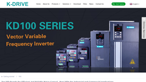
Best Vfd Manufacturers and Suppliers, Factory OEM Quotes | K-Drive
Website: thefrequencyinverters.com
SHENZHEN K-EASY AUTOMATION CO., LTD. (K-Drive) manufactures Variable Frequency Drives (VFDs) for industrial motor speed control and automation. Key VFD product lines include: KD700 Series (book-type, high-performance vector inverter), KD600 Series (vector inverter with K-DRIVE technology), KD600M Series (high-performance vector inverter), and KD600/IP65 IP54-rated waterproof VFDs for harsh environ…

Industry’s Top 10 VFD Cable Manufacturers of 2023
Website: grandoceanmarine.com
VFD (Variable Frequency Drive) cables are specialized electrical wires designed for VFD systems that control electric motor speed and torque in industrial automation applications. Key technical specifications include: RFI (Radio Frequency Interference) and EMI (Electromagnetic Interference) reduction capabilities ensuring efficient and reliable system operation; high voltage spike resistance and r…

Analysis of the Top 25 Variable Frequency Drive (VFD) Companies …
Website: finance.yahoo.com
No product details extracted. The provided text is a Yahoo error page (‘Oops, something went wrong’) containing only navigation menus and links to general Yahoo sections (News, Health, Shopping, etc.), with no substantive content regarding solar inverters, VFDs, variable frequency drives, or industrial automation equipment.
B2B Engineering FAQs About Variable Frequency Drive Speed Control
-
How does VFD speed control leverage the Affinity Laws to reduce energy consumption in centrifugal pumping systems?
In centrifugal applications, energy consumption follows the cube of the speed (P ∝ N³). By reducing motor speed from 100% to 80% using a VFD, power draw drops by approximately 50%, not 20%. For agricultural irrigation or industrial fluid handling, this translates to 40–70% energy savings compared to throttling valves or across-the-line operation. Modern VFDs also optimize motor magnetization current based on load torque, further improving efficiency at partial loads common in solar pumping or variable-demand processes. -
What is the technical distinction between V/Hz control and Sensorless Vector Control (SVC) for high-torque motor applications?
V/Hz control maintains a constant voltage-to-frequency ratio, suitable for variable torque loads like fans and standard pumps. However, for high-breakaway torque scenarios—such as deep-well submersible pumps or positive displacement pumps—Sensorless Vector Control independently regulates flux and torque by modeling motor current vectors. SVC provides 150–200% starting torque at 0.5 Hz without encoder feedback, critical for solar pump inverters starting under low irradiance conditions or overcoming static head pressure. -
How do Solar Pump Inverters (PV VFDs) differ from standard grid-tied VFDs regarding DC input handling and Maximum Power Point Tracking (MPPT)?
Unlike AC-input VFDs that rectify grid power, solar pump inverters accept high-voltage DC directly from PV arrays (typically 200–800 VDC). They integrate specialized MPPT algorithms that continuously adjust the DC operating point to extract maximum available solar energy (typically 98–99% tracking efficiency). These drives include dry-run protection, tank-full detection, and automatic wake/sleep functions based on irradiance levels—features absent in conventional industrial VFDs designed for stable AC supplies. -
What harmonic mitigation strategies should EPC contractors implement when deploying multiple VFDs in large-scale agricultural or industrial installations?
Multiple VFDs can inject harmonic currents (THD) into the grid, causing transformer overheating and voltage distortion. For projects with >20 drives, specify DC link chokes (3–5% impedance) or active front-end (AFE) regenerative drives. In solar pumping stations, distributed AC line reactors (2–3%) reduce cable-reflected voltage spikes and harmonics. Compliance with IEEE 519 or IEC 61000-3-6 requires calculating cumulative THD during the design phase, particularly when VFDs share supply transformers with sensitive control equipment. -
How do acceleration and deceleration ramp settings in VFDs prevent mechanical stress and water hammer in long-distance pipeline systems?
Instantaneous motor starts generate 7–8x nominal torque, risking shaft coupling failure and pressure surges. VFDs allow programmable S-curve ramps (typically 5–30 seconds) that gradually increase pump speed, eliminating hydraulic shock. For high-inertia systems or downhill pumping, integrating DC injection braking or dynamic braking resistors prevents column separation and water hammer during deceleration. Advanced pump control software can also detect no-flow conditions and trigger controlled shutdown sequences to protect pipeline integrity. -
What are the critical derating factors when sizing VFDs for submersible motors in high-temperature or high-altitude agricultural environments?
VFDs must be derated 1% per 100m above 1,000m altitude due to reduced air cooling capacity, and 2.5% per 10°C above 40°C ambient. For submersible pumps, account for cable capacitance—long motor leads (>50m) require output reactors or dV/dt filters to prevent reflected wave voltage spikes that damage motor insulation. In solar applications, size the VFD at 110–120% of motor FLA to handle PV array voltage fluctuations and ensure continuous operation during partial shading without nuisance tripping. -
How do modern VFDs integrate with SCADA and IoT platforms for remote monitoring in off-grid solar pumping and industrial automation?
Contemporary VFDs feature embedded Modbus RTU/TCP, CANopen, or EtherNet/IP protocols for seamless PLC integration. For remote agricultural sites, VFDs with built-in GPRS/4G modules transmit real-time data—flow rates, PV power input, motor temperature, and fault codes—to cloud-based SCADA systems. This enables predictive maintenance algorithms to detect bearing wear or pump cavitation trends, while allowing EPC contractors to perform firmware updates and parameter adjustments remotely, reducing OPEX for geographically dispersed solar pumping stations. -
What ingress protection (IP) and environmental hardening features are essential for VFDs deployed in harsh agricultural or desert solar environments?
Agricultural and solar installations demand IP65 or IP66 enclosures to protect against dust, irrigation spray, and humidity. Conformal coating on PCBs prevents corrosion from ammonia (livestock facilities) or salt air (coastal solar farms). Thermal management via external heatsinks or liquid cooling maintains operation at ambient temperatures up to 55°C. Additionally, integrated surge protection devices (SPDs) rated for Category C2/C3 (10–20kA) are critical for solar pump inverters exposed to lightning-induced transients in open-field PV arrays.
Disclaimer
⚠️ Important Disclaimer
The information provided in this guide is for educational purposes. Industrial applications and electrical engineering projects carry inherent risks. B2B buyers and contractors must conduct thorough technical due diligence and verify regional compliance before installation or procurement.
Conclusion: Partnering with Boray Inverter for Variable Frequency Drive Speed Control
Variable frequency drive speed control represents more than an operational upgrade—it is a strategic imperative for modern industrial and agricultural infrastructure. By precisely matching motor output to load demand, VFDs deliver measurable reductions in energy consumption, extend equipment lifecycle, and enable the process automation required for Industry 4.0 and sustainable agriculture. Whether optimizing centrifugal pumps in irrigation networks or fine-tuning conveyor systems in manufacturing plants, the implementation of intelligent speed control technology directly correlates with enhanced profitability and reduced carbon footprint.
However, the efficacy of these systems depends fundamentally on the quality and engineering precision of the drive hardware itself. This is where Shenzhen Boray Technology Co., Ltd. distinguishes itself as a premier manufacturing partner. As an innovative specialist in Solar Pumping and Motor Control Solutions based in China, Boray Inverter combines deep technical expertise with robust production capabilities to serve the exacting requirements of EPC contractors, system integrators, and automation distributors worldwide.
Boray’s competitive advantage lies in its intensive R&D investment—engineers comprise 50% of the workforce—mastering advanced PMSM and IM vector control algorithms that ensure superior torque response and energy efficiency across variable load conditions. With two state-of-the-art production lines and rigorous 100% full-load testing protocols, every unit meets stringent international standards for reliability in harsh agricultural and industrial environments. From solar-powered irrigation projects in arid regions to precision manufacturing lines, Boray’s solutions have earned global trust through consistent performance and technical adaptability.
For organizations seeking to deploy high-performance VFD speed control systems, Boray Inverter offers not just standardized products but engineered customization to meet specific application demands. Contact the team at borayinverter.com today to discuss your project specifications, request technical documentation, or obtain competitive wholesale quotations for your next automation or solar pumping initiative.