Introduction: Sourcing Variable Frequency Drive Wiring for Industrial Use
In industrial automation and solar pumping infrastructure, the margin between peak operational efficiency and catastrophic system failure frequently hinges on wiring integrity. As Variable Frequency Drives (VFDs) assume mission-critical roles across agricultural irrigation, heavy manufacturing, and renewable energy systems, proper wiring practices transcend basic installation protocols—they become strategic imperatives for system reliability and energy optimization. A single grounding deficiency, undersized thermal-magnetic breaker, or improperly shielded motor lead can induce destructive electromagnetic interference, trigger nuisance tripping, or compromise IGBT power components, translating to significant downtime costs for EPC contractors and automation distributors managing complex global supply chains.
This comprehensive guide demystifies the technical complexities of VFD wiring for demanding industrial and solar applications. We dissect essential configuration topologies, from fundamental three-phase motor terminations and PE grounding protocols to sophisticated PLC integration and external control device interfacing. Critical specifications examined include cable sizing algorithms, steel conduit separation requirements per NEC and IEC standards, and dV/dT filtering for long-cable solar pump installations exceeding 250 feet. For procurement specialists and systems integrators, we evaluate manufacturer selection frameworks, emphasizing UL/CE compliance certifications, protection device coordination, and the distinction between consumer-grade and industrial-rated wiring solutions. Whether sourcing components for multi-megawatt agricultural projects or designing motor control centers for process automation, mastering these wiring fundamentals ensures seamless integration, regulatory compliance, and maximized lifecycle ROI across diverse operational environments.
Article Navigation
- Top 3 Variable Frequency Drive Wiring Manufacturers & Suppliers List
- Introduction: Sourcing Variable Frequency Drive Wiring for Industrial Use
- Technical Types and Variations of Variable Frequency Drive Wiring
- Key Industrial Applications for Variable Frequency Drive Wiring
- Top 3 Engineering Pain Points for Variable Frequency Drive Wiring
- Component and Hardware Analysis for Variable Frequency Drive Wiring
- Manufacturing Standards and Testing QC for Variable Frequency Drive Wiring
- Step-by-Step Engineering Sizing Checklist for Variable Frequency Drive Wiring
- Wholesale Cost and Energy ROI Analysis for Variable Frequency Drive Wiring
- Alternatives Comparison: Is Variable Frequency Drive Wiring the Best Choice?
- Core Technical Specifications and Control Terms for Variable Frequency Drive Wiring
- Future Trends in the Variable Frequency Drive Wiring Sector
- B2B Engineering FAQs About Variable Frequency Drive Wiring
- Disclaimer
- Conclusion: Partnering with Boray Inverter for Variable Frequency Drive Wiring
Technical Types and Variations of Variable Frequency Drive Wiring
Selecting the appropriate VFD wiring architecture is critical for system reliability, EMI compliance, and long-term operational efficiency. The configuration varies significantly based on your power source infrastructure, motor distance, and control precision requirements. Below are the four primary technical variations employed in industrial and agricultural automation, ranging from standard grid-connected setups to specialized solar pumping configurations.
| Type | Technical Features | Best for (Industry) | Pros & Cons |
|---|---|---|---|
| Single-Phase Input (230V/240V) | • 2-wire + PE ground input • Breaker sized at 1.5× input FLA • Motor wires in separate steel conduit • Typically limited to ≤3 HP (2.2 kW) |
Small-scale agriculture, rural irrigation, commercial HVAC retrofits | Pros: Utilizes existing single-phase infrastructure; lower installation cost Cons: Higher input current draw; limited power range; requires input derating |
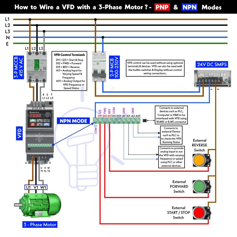
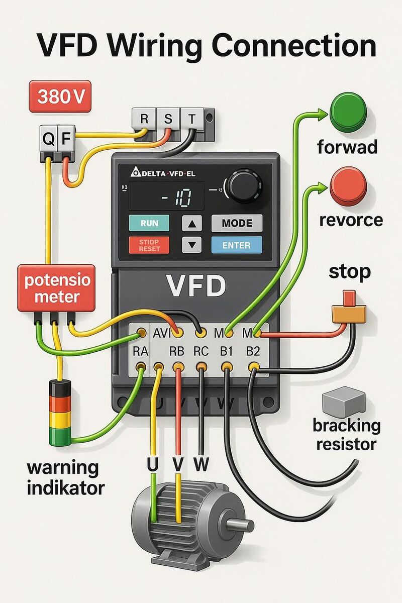
| Three-Phase Input (380V-480V) | • 3-wire + PE ground input • Full rated capacity utilization • Dedicated thermal-magnetic protection per drive • Strict conduit segregation (input/output/control) |
Manufacturing, water treatment plants, heavy industrial automation | Pros: Balanced utility loading; full power availability; standard industrial practice Cons: Requires 3-phase utility access; higher infrastructure investment |
| Solar DC Input (PV Direct) | • DC input 200V–800VDC (no AC rectifier stage) • Integrated MPPT control circuitry • DC arc-fault protection & isolation required • Motor output: 3-phase AC (T1, T2, T3) |
Off-grid agriculture, remote solar pumping, EPC irrigation projects | Pros: Eliminates grid dependency; zero fuel costs; operates without batteries Cons: Weather-dependent output; requires specialized DC fusing; voltage fluctuation management |
| Long-Distance Motor Run with Filtering | • Output reactor (>250 ft / 76m) • dV/dT filter (500–1000 ft / 150–300m) • Separate steel conduit mandatory • Reflected wave protection at motor terminals |
Mining operations, large agricultural estates, municipal distribution networks | Pros: Allows remote motor placement; prevents insulation damage from voltage spikes Cons: Additional component costs; voltage drop calculations required; larger conduit sizing |
Single-Phase Input (230V/240V) Wiring Configuration
This configuration is engineered for installations where three-phase utility power is unavailable, common in rural agricultural settings or legacy commercial buildings. Critical wiring requirements include installing a thermal-magnetic circuit breaker sized at 1.5 times the VFD’s input amperage to handle inrush currents during capacitor charging. Input conductors must be rated for the higher current draw inherent to single-phase operation—typically 1.73 times the current of an equivalent three-phase system.
Motor output wiring (T1, T2, T3) must be run in dedicated steel conduit separated from both the AC input power and any control wiring to prevent capacitive coupling and noise interference. As specified in standard installation protocols, never install a contactor between the drive and motor; if a disconnect switch is required, it must be mechanically interlocked to operate only when the VFD is in a STOP state to prevent arcing damage to the IGBT output stage.
Three-Phase Input Industrial Wiring
The standard industrial configuration provides optimal performance for motors ranging from 1 HP to 500+ HP. Each VFD requires its own dedicated circuit breaker; combining multiple drives on a single breaker necessitates individual downstream fuses or MCBs for each unit. Input AC line wires should be routed in conduit from the breaker panel, with multiple VFDs permitted in a single input conduit if necessary.
Output power segregation is paramount: motor wires from each VFD to its respective motor must occupy separate steel conduits, isolated from control signals and incoming AC power. This prevents crosstalk between drives and protects sensitive PLC communication lines from electromagnetic interference. The drive must be grounded on the terminal marked PE (Protective Earth) using a dedicated ground conductor sized per local electrical codes, not relying on conduit alone for grounding.
Solar DC Input (PV Direct) Wiring
As a specialized configuration for solar pump inverters—core to Boray’s product portfolio—this architecture eliminates the traditional AC input stage. The VFD accepts DC power directly from photovoltaic arrays, with wiring requirements focused on DC arc-fault protection and proper conductor sizing for 200V–800VDC ranges. Unlike AC input systems, DC wiring requires specialized connectors rated for high-voltage DC and continuous operation in outdoor environments.
The motor output side maintains standard three-phase AC wiring practices (T1, T2, T3), but with enhanced filtering to handle the variable input voltage from solar irradiance fluctuations. DC input wiring must include isolation switches and fusing on both positive and negative legs, sized according to the array’s short-circuit current (Isc) rather than motor FLA. This configuration is ideal for EPC contractors deploying off-grid irrigation systems where grid extension is cost-prohibitive.
Long-Distance Motor Run with Output Filtering
When motor cable runs exceed 250 feet (76 meters), standard VFD output wiring becomes susceptible to reflected wave phenomena and voltage spike damage. This variation requires installing an output reactor between the VFD and motor for runs of 250–500 feet, or a dV/dT filter for distances up to 1000 feet (300 meters). These components dampen the rate of voltage rise (dV/dt) that causes motor insulation stress in long cable runs.
Wiring implementation demands rigorous conduit planning: motor cables must run in separate steel conduit away from all other wiring, and the reactor or filter requires its own enclosure with adequate ventilation. For distances beyond 1000 feet, consider using a load reactor at the motor terminal box in addition to the drive-mounted reactor. This architecture is essential for mining applications and large agricultural estates where the control room is centralized but pumping stations are distributed across vast distances.
Installation Note: Regardless of configuration type, always verify that parameter P107 (voltage class) is programmed to match your specific motor voltage—set to “Low” for 120V/208V/400V systems or “High” for 230V/480V/575V systems—to ensure proper PWM output waveform generation and motor protection.
Key Industrial Applications for Variable Frequency Drive Wiring
Variable Frequency Drive (VFD) wiring configurations must be tailored to sector-specific operational demands, environmental stressors, and motor-to-drive distances. While core principles—such as dedicated input breakers sized at 1.5x the drive’s input amperage and isolated steel conduits for motor output cables—remain constant, each industry presents unique cabling challenges ranging from deep-well submersible installations to high-vibration mineral processing environments.
| Sector | Application | Energy Saving Value | Sourcing Considerations |
|---|---|---|---|
| Agriculture & Solar Pumping | PV-powered irrigation systems & deep-well submersible pumps | 30–50% reduction vs. diesel pumps; 95%+ MPPT efficiency | IP65/NEMA 4X enclosures for outdoor termination; DC input wiring gauges for solar arrays; output reactors for vertical lifts >250ft |
| Water/Wastewater Treatment | Municipal pumping stations, aeration blowers & filtration systems | 20–40% via flow/pressure optimization; reduced water hammer | Dedicated steel conduit for motor cables (separate from AC input/control wiring); EMC filtering; SCADA/PLC integration wiring |
| HVAC & Building Automation | Chilled water pumps, cooling towers & air handling units | 30–60% through variable flow control; soft-start benefits | Low-harmonic input wiring; isolated 24VDC control circuits; shielded communication cables for BMS integration |
| Cement & Heavy Industry | Rotary kiln drives, conveyors, crushers & ball mills | 15–25% via torque control; reduced mechanical wear | dV/dT filters for motor leads 500–1000ft; vibration-resistant terminal lugs; thermal-magnetic breakers (1.5x input amps) |
| Manufacturing Processing | Plastic extruders, industrial mixers & precision machine tools | 20–35% via precise speed/torque regulation | Shielded encoder feedback wiring; isolated analog I/O (0–10V/4–20mA); robust PE grounding to prevent EMI |
Agriculture & Solar Pumping
In solar pumping applications, VFD wiring must bridge the gap between photovoltaic (PV) DC inputs and long-distance AC motor runs. For deep-well submersible pumps—common in irrigation projects—motor cables often exceed 250 feet, necessitating output reactors to mitigate voltage reflection and protect motor insulation. When sourcing drives for agricultural EPC projects, specify units with IP65-rated terminal enclosures to withstand outdoor humidity and dust. DC input wiring from PV arrays requires proper gauge sizing to minimize voltage drop, while AC output wiring to submersible motors must utilize continuous ground bonding to the PE terminal, ensuring safety in wet borehole environments.
Water/Wastewater Treatment
Municipal pumping stations typically cluster multiple VFDs within Motor Control Centers (MCCs), making wiring segregation critical. Input AC power to each drive requires individual thermal-magnetic breakers, sized at 1.5 times the drive’s input amperage to handle inrush currents. Per NEC and IEC standards, motor output wires must run in separate steel conduits away from incoming AC power and control wiring to prevent electromagnetic interference with SCADA systems. For applications involving aeration blowers or filtration pumps, source VFDs with integrated EMC filters and ensure control wiring (for pressure transducers and flow sensors) utilizes shielded twisted pairs with single-point grounding to maintain signal integrity in noisy electrical rooms.
HVAC & Building Automation
HVAC systems demand seamless integration between VFDs and Building Management Systems (BMS) or PLCs. Control wiring for 0–10V or 4–20mA signals requires isolated analog inputs and shielded cables to prevent feedback loops. When sourcing drives for chilled water or cooling tower applications, prioritize models with low-harmonic input stages to reduce line distortion, particularly when multiple drives share electrical infrastructure. Critical wiring note: While bypass contactors are sometimes requested for redundancy, no contactor should be installed between the VFD and motor for operational switching—disconnect switches must only be actuated when the drive is in a STOP state to avoid power component damage.
Cement & Heavy Industry
Heavy industrial environments subject VFD wiring to extreme vibration and long cable runs. In cement plants, motors driving kilns, conveyors, or crushers may be located 500–1000 feet from the drive, requiring dV/dT filters to protect against reflected wave phenomena that damage motor windings. Sourcing considerations include heavy-duty terminal lugs capable of withstanding thermal cycling and vibration, as well as output reactors for runs exceeding 250 feet. Input wiring must utilize thermal-magnetic breakers sized appropriately for the high inertial loads typical in crushing and grinding applications, with all conduit entries sealed against cement dust ingress.
Manufacturing Processing
Precision manufacturing applications—such as extrusion or CNC machining—require VFD wiring that prioritizes signal integrity and electromagnetic compatibility. Encoder feedback cables must be double-shielded and routed perpendicular to power cables to prevent position signal degradation. Control wiring for emergency stop circuits and PLC interlocks should utilize 24VDC isolated inputs to avoid ground loop issues. When sourcing for these environments, verify that drive terminals accommodate fine-stranded control wires alongside heavy-gauge power cables, and ensure the PE grounding terminal provides a low-impedance path to facility ground to dissipate high-frequency noise generated by IGBT switching.
Top 3 Engineering Pain Points for Variable Frequency Drive Wiring
Scenario 1: Electromagnetic Interference (EMI) and Control Signal Corruption in Multi-Drive Environments
The Problem: In industrial facilities and large-scale solar pumping stations, engineers frequently encounter erratic VFD behavior, PLC communication faults, and encoder signal drift when motor output cables are routed alongside low-voltage control wiring or RS-485 communication lines. The high-frequency switching of IGBTs generates significant electrical noise that inductively couples into adjacent circuits, causing nuisance tripping, speed reference errors, and loss of remote monitoring capabilities—critical failures in unmanned agricultural automation projects.
The Solution: Implement strict cable segregation per IEC 61800-3 and NEC Article 430 standards. Route motor power conductors (T1, T2, T3) in dedicated steel conduits physically separated from control cabling by a minimum 12-inch gap or metallic barriers. Utilize shielded twisted pair cables for control signals and PLC I/O, grounding shields at the VFD terminal block only to prevent ground loops. For solar pump inverters operating in harsh EMC environments, specify drives with integrated Class A or Class B EMC filters and ensure robust PE grounding to the dedicated protective earth terminal to suppress conducted emissions.
Scenario 2: Voltage Reflection and Motor Insulation Stress in Long Cable Runs
The Problem: Remote solar irrigation sites and decentralized industrial processes often require VFD-to-motor distances exceeding 250 feet (75 meters). Long motor cables create impedance mismatches between the drive’s PWM output and the motor windings, generating voltage reflection phenomena that can produce 2-4x nominal voltage spikes at motor terminals. This leads to premature insulation failure, bearing currents (electrical fluting), and catastrophic motor damage—particularly costly in submersible pump applications where motor replacement involves significant downtime and labor.
The Solution: For cable runs between 250-500 feet, install output reactors (load reactors) between the VFD output terminals and the motor to increase rise time and mitigate dV/dt stress. For distances of 500-1000 feet, deploy dV/dt filters or sinusoidal output filters to protect motor winding insulation. Size reactors based on drive output current rating and cable capacitance. In solar pumping projects, position VFD enclosures strategically to minimize cable lengths, or specify inverter-duty motors with Class F or H insulation systems and isolated bearing configurations to handle reflected wave voltages.
Scenario 3: Protection Coordination Failures and Catastrophic Miswiring Events
The Problem: EPC contractors and maintenance teams face significant liability when upstream circuit breakers nuisance-trip during VFD capacitor charging inrush, or when technicians accidentally connect incoming AC line power to the drive’s output terminals (T1, T2, T3)—resulting in immediate drive destruction and potential arc flash hazards. Additionally, daisy-chaining multiple VFDs on a single breaker without individual protection creates cascading failure risks and complicates fault isolation in agricultural automation systems.
The Solution: Size thermal-magnetic circuit breakers at 1.5 times the VFD’s input amperage (not the output FLA) with fast-acting trip characteristics to accommodate inrush current while providing short-circuit protection. Install dedicated branch circuit protection for each drive; if economic constraints require shared bus configurations, add individual fuses or miniature circuit breakers downstream of the main breaker for each unit. Implement mechanical keying or color-coded terminal shrouds to prevent line-to-output miswiring during commissioning. For solar pump VFDs, verify DC input polarity and AC output phase sequence before energization to prevent reverse rotation in submersible pumps, and ensure disconnect switches between drive and motor are only operated when the drive is in STOP state to avoid damage to power components.
Component and Hardware Analysis for Variable Frequency Drive Wiring
The reliability and performance of any Variable Frequency Drive (VFD) installation—whether deployed in harsh agricultural solar pumping stations or continuous-duty industrial motor control—depends fundamentally on the quality of its internal power electronics and their integration with external wiring infrastructure. While external wiring practices (cable shielding, grounding, and circuit protection) form the system’s nervous system, the internal components constitute the heart and brain of the drive. For EPC contractors and automation engineers specifying equipment for mission-critical applications, understanding the hardware architecture beneath the enclosure is essential for predicting Mean Time Between Failures (MTBF) and optimizing Total Cost of Ownership (TCO).
Power Semiconductor Architecture
At the core of every VFD lies the IGBT (Insulated Gate Bipolar Transistor) power module, responsible for the high-frequency switching that synthesizes variable-frequency output from DC bus voltage. In solar pumping applications, where DC input from PV arrays can fluctuate between 200VDC and 800VDC depending on irradiance, the IGBT module must exhibit exceptional dv/dt ruggedness and low switching losses. Boray Inverter utilizes 6th-generation trench-gate field-stop IGBTs with integrated anti-parallel diodes, capable of handling surge currents up to 200% of nominal rating—critical for starting high-inertia centrifugal pumps in agricultural irrigation systems.
The input rectifier bridge and DC link capacitors form the front-end power stage. For solar pump inverters specifically, the rectifier must handle not only grid-connected AC but also direct DC injection from photovoltaic arrays without modification. High-grade rectifiers employ soft-recovery diodes to minimize electromagnetic interference (EMI), reducing the burden on external EMI filters and shielded motor cables. The DC link capacitors, typically metallized polypropylene film types in premium drives (as opposed to electrolytic), must exhibit low Equivalent Series Resistance (ESR) to handle high ripple currents generated by IGBT switching, particularly when operating at low speeds where DC bus ripple is most pronounced.
Control and Protection Electronics
The Digital Signal Processor (DSP) or Motor Control Unit (MCU) serves as the drive’s command center, executing complex vector control algorithms and real-time protection logic. In advanced solar pump inverters, this processor manages Maximum Power Point Tracking (MPPT) algorithms alongside motor control, requiring computational throughput exceeding 100 MIPS. Quality indicators include industrial-grade temperature specifications (-40°C to +85°C) and conformal coating compliance with IPC-CC-830 standards, ensuring immunity to humidity, dust, and corrosive gases common in agricultural environments.
Gate driver circuits interface between the DSP and power modules, providing isolated voltage pulses to IGBT gates. These employ optocouplers or magnetic isolators with Common Mode Transient Immunity (CMTI) exceeding 25 kV/μs, preventing latch-up during rapid switching events that characterize long-cable installations (often exceeding 250 feet in solar pumping arrays).
Thermal Management Infrastructure
Thermal design directly impacts wiring reliability. Aluminum heatsinks with anodized finishes and optimized fin geometries must maintain thermal resistance below 0.5°C/W to keep IGBT junction temperatures below 125°C under full load. For IP65-rated solar pump inverters deployed in desert climates, passive cooling via heat pipes or liquid-cooled cold plates often replaces forced-air systems, eliminating fan failure modes but requiring specific enclosure wiring clearances to ensure convective airflow.
Component Analysis Matrix
| Component | Function | Quality Indicator | Impact on Lifespan |
|---|---|---|---|
| IGBT Power Module | High-frequency switching for PWM waveform generation; converts DC bus voltage to variable frequency AC output | Low thermal resistance (Rth(j-c) < 0.6 K/W), high dv/dt ruggedness (>5kV/μs), 6th generation trench-gate technology, and integrated temperature sensors | Thermal cycling fatigue is the primary failure mode; quality modules extend lifespan from 40,000 to 100,000+ hours under full load; poor quality increases risk of shoot-through faults damaging motor windings |
| DSP Controller | Executes vector control algorithms, fault protection logic, and MPPT (for solar); generates precise PWM signals | 32-bit floating-point architecture (>100MHz), industrial temperature range (-40°C to +85°C), conformal coating IPC-CC-830, and hardware watchdog timers | Determines immunity to electrical noise and control stability; high-grade DSPs prevent nuisance tripping and premature shutdowns that stress contactors and breakers |
| DC Link Capacitor | Filters rectified DC voltage, absorbs ripple current from IGBT switching, provides energy storage for motor deceleration | Low ESR (<10mΩ), high ripple current capacity (>150% rated), metalized polypropylene film construction (vs. electrolytic), and self-healing dielectric | Film capacitors offer 100,000 hours vs. 20,000 hours for electrolytic; critical for solar applications with wide temperature swings; failure modes include capacitance loss leading to bus voltage instability |
| Thermal Management System (Heatsink/Fan) | Dissipates switching losses (2-3% of power) from IGBTs and rectifiers; maintains junction temperatures below Tj(max) | Aluminum alloy 6063-T5 with anodized finish, thermal resistance <0.5°C/W; ball-bearing fans with MTBF >50,000 hours or passive heat-pipe systems | Every 10°C reduction in heatsink temperature doubles component lifespan; critical in dusty agricultural environments where fan failure causes thermal runaway |
| Input Rectifier Bridge | Converts incoming AC (grid) or handles direct DC (solar) to charge the DC bus; manages inrush current | High surge current capability (IFSM >200A), low forward voltage drop (<1.1V), soft-recovery characteristics, and 1600V reverse voltage rating | Prevents thermal runaway during voltage sags; quality rectifiers reduce stress on upstream wiring and breakers; failure can cause short-circuit conditions affecting supply cables |
| Pre-Charge Circuit | Limits inrush current to DC bus capacitors during startup; prevents contactor welding and voltage dips on supply lines | NTC thermistors with high energy capacity (E25 >100J) or active pre-charge with IGBT bypass and current limiting resistors | Eliminates mechanical stress on capacitors and contactors; extends contactor life by 10x; prevents nuisance tripping of upstream breakers sized at 1.5x input current |
| EMI Filter | Suppresses conducted emissions from switching IGBTs; protects control circuits and prevents PLC interference | High permeability nanocrystalline cores, high dv/dt withstand (>10kV/μs), and low leakage current (<3.5mA) compliant with IEC 61800-3 | Prevents insulation degradation in motor windings and adjacent control wiring; reduces bearing currents that damage motor bearings over time; poor filtering necessitates expensive shielded cables |
Integration with External Wiring Practices
The quality of internal components directly dictates external wiring requirements. High-performance IGBT modules with gentle dv/dt switching characteristics (achieved through advanced gate driver algorithms) reduce the need for output reactors in cable runs up to 500 feet—common in distributed solar pumping arrays. Conversely, drives utilizing lower-grade components with aggressive switching edges require dV/dT filters or sinusoidal output filters to prevent motor terminal overvoltage and premature insulation failure.
For EPC contractors, specifying VFDs with film capacitors rather than electrolytic types eliminates the need for frequent capacitor replacement in remote solar installations, where service access is costly. Similarly, drives employing passive cooling architectures simplify enclosure wiring by removing fan power circuits and thermal switch interlocks, though they require larger gauge power wiring to minimize resistive heating in the absence of forced air cooling.
In solar pump inverter applications specifically, the pre-charge circuit quality becomes paramount when switching between PV array zones. Robust pre-charge logic prevents arcing in external DC contactors and minimizes stress on PV array wiring during morning startup sequences when irradiance ramps rapidly.
Understanding these component-level distinctions enables engineers to specify drives that align wiring protection schemes—such as breaker sizing at 1.5x input current and separate conduit requirements for motor cables—with the actual hardware stress factors, ensuring system longevity across 20+ year operational lifespans in demanding agricultural and industrial environments.
Manufacturing Standards and Testing QC for Variable Frequency Drive Wiring
At Boray Inverter, manufacturing excellence for Variable Frequency Drives (VFDs) and Solar Pump Inverters extends beyond assembly—it encompasses a rigorous validation ecosystem designed to ensure wiring integrity, thermal resilience, and long-term reliability in harsh agricultural and industrial environments. Given that wiring failures account for a significant percentage of field returns in motor control applications, our Quality Control (QC) protocols are engineered to eliminate infant mortality and guarantee performance under extreme thermal cycling, humidity, and full-load conditions.
PCB Conformal Coating and Environmental Protection
The foundation of VFD wiring reliability begins at the Printed Circuit Board (PCB) level. All control and power PCBs undergo automated selective conformal coating using acrylic or silicone-based compounds (meeting IPC-CC-830 standards) to provide moisture and dust insulation. This is critical for solar pumping installations where condensation and airborne particulates are prevalent. Our process includes:
- UV-traceable coating application: Ensuring 100% coverage on high-voltage traces and terminal connections without masking critical test points.
- Triple-layer protection: Primary solder mask, secondary conformal coating, and tertiary potting for terminal blocks in high-vibration agricultural environments.
- Insulation Resistance (IR) Testing: Post-coating megohm testing at 500VDC to verify dielectric integrity between power terminals and control circuitry, preventing leakage currents that compromise EMC compliance.
High-Temperature Aging and Burn-in Protocols
To simulate the thermal stress of continuous solar pumping operations (where ambient temperatures can exceed 50°C), every VFD undergoes High-Temperature Operating Life (HTOL) testing:
- Burn-in Duration: 48 to 72 hours at 85°C ambient with 100% rated load applied to power terminals.
- Dynamic Thermal Cycling: Rapid temperature transition testing (-20°C to +70°C) to validate solder joint integrity on IGBT modules and terminal connections, preventing cold-solder failures during seasonal temperature swings.
- Thermal Imaging Verification: Infrared scanning of wire terminations and bus bars during burn-in to detect high-resistance connections before shipment.
100% Full-Load Production Testing
Unlike sample-based QC, Boray Inverter implements 100% full-load functional testing on every unit produced. This protocol validates not only the wiring harness integrity but also the complete power path under operational stress:
- Motor Emulation vs. Dynamometer Testing: Units are tested against actual induction motors (up to the drive’s rated HP) as well as regenerative loads to verify torque response and braking chopper functionality.
- Multi-Point Efficiency Validation: Testing at 25%, 50%, 75%, and 100% load to ensure wiring losses remain within IEC 61800-9-2 efficiency class standards.
- Input/Output Terminal Integrity: High-current verification (1.5x rated current for 60 seconds) on R/S/T input and U/V/W output terminals to confirm crimp quality and thermal stability of power wiring.
Wiring Harness and Terminal Assembly QC
The physical wiring infrastructure—terminal blocks, bus bars, and internal harnesses—undergoes specialized mechanical and electrical validation:
- Automated Wire Processing: Crimping force monitoring and pull-test verification (per IPC/WHMA-A-620) for every power and control wire to ensure gas-tight connections resistant to oxidation.
- Torque Seal Validation: All terminal screws are torque-verified using calibrated electric drivers, with tamper-evident seals applied to prevent field loosening in high-vibration pump applications.
- Hi-Pot (Dielectric Withstand) Testing: Application of 2kVAC+ (depending on rated voltage) between power and control circuits for 60 seconds to detect insulation breakdowns in wiring insulation.
Environmental Stress Screening (ESS)
For solar pump inverters destined for outdoor installation, additional environmental validation ensures wiring integrity against the elements:
- Salt Spray Testing: 96-hour ASTM B117 exposure for coastal agricultural projects, validating corrosion resistance of plated terminals and grounding points.
- IP Rating Verification: Pressurized dust and water ingress testing (IP65/IP66) on completed enclosures to ensure cable gland sealing and conduit entry points maintain environmental protection.
- Vibration and Shock Testing: IEC 60068-2-6 random vibration testing (5-500Hz) to simulate transportation and pump-mounting stresses on internal wiring harnesses.
Compliance Framework and Traceability
All manufacturing processes adhere to international standards ensuring global deployability:
- ISO 9001:2015 Certification: Documented quality management systems covering supplier qualification, incoming material inspection (for copper wire and magnetic components), and continuous process improvement.
- CE Compliance: Full adherence to EN 61800-5-1 (safety requirements), EN 61800-3 (EMC), and Low Voltage Directive (2014/35/EU) for European solar projects.
- IEC 61000-4-x Immunity: Verified wiring shielding effectiveness against surge, burst, and conducted disturbances—critical for VFDs operating near grid-tied solar inverters.
- MES Traceability: Manufacturing Execution System tracking of every wire harness batch, PCB serial number, and test data curve, enabling rapid root-cause analysis and 5-year warranty support.
By integrating these manufacturing standards and QC protocols, Boray Inverter ensures that every VFD and Solar Pump Inverter delivered to EPC contractors and agricultural integrators exhibits the wiring integrity and thermal stability required for decades of continuous operation in the world’s most demanding environments.
Step-by-Step Engineering Sizing Checklist for Variable Frequency Drive Wiring
Before initiating physical installation, complete this engineering validation protocol to ensure NEC/CEC compliance, optimize motor-drive compatibility, and mitigate EMI risks in agricultural or industrial environments. This checklist applies to standard VFDs and solar pump inverter configurations.
Phase 1: Input Power Infrastructure Sizing
1. Overcurrent Protection Calculation
– [ ] Calculate breaker rating: Input Amperage × 1.5 (minimum). Use thermal-magnetic, fast-acting circuit breakers only.
– [ ] Verify individual breaker dedication: Each VFD requires a dedicated upstream breaker. If combining multiple drives on a single feeder breaker, install individual fuses or MCBs downstream for each unit.
– [ ] Confirm breaker interrupting rating exceeds available fault current at installation point.
2. Supply Conductors and Raceway
– [ ] Size input conductors per NEC Table 310.16 (or local equivalent) based on VFD input current, with 75°C insulation minimum.
– [ ] Run input AC lines in dedicated metallic conduit from breaker panel to drive enclosure. Multiple VFD inputs may share a single conduit if derated per conduit fill tables.
– [ ] Critical Verification: Confirm line voltage matches VFD nameplate rating (e.g., 230V vs. 480V) and motor voltage parameter (P107 equivalent: Set 0 for 120/208/400V; Set 1 for 230/480/575V).
Phase 2: Motor Compatibility and Output Circuit Design
3. Motor Full Load Ampere (FLA) Matching
– [ ] Record motor nameplate FLA and voltage.
– [ ] Program overload protection (P108 equivalent parameter) using formula:
(Motor FLA × 100) ÷ Drive Output Amp Rating
Example: 10A motor on 15A drive = (10×100)/15 = 66.7% setting.
– [ ] Verify motor insulation rating is sufficient for drive output (minimum Class F for modern IGBT drives).
4. Output Cable Sizing and Isolation
– [ ] Size motor conductors per drive output ampacity, maintaining voltage drop below 3% at rated current.
– [ ] Mandatory Separation: Run motor wires (T1, T2, T3) in separate steel conduit isolated from control wiring and input AC power. This prevents capacitive coupling and cross-talk between drives.
– [ ] Distance-Based Filtering:
– [ ] Cable run >250 ft (76m): Install output load reactor between drive and motor.
– [ ] Cable run 500–1000 ft (152–304m): Install dV/dT filter (reactor alone insufficient).
– [ ] Cable run >1000 ft: Consult factory for sine wave filter requirements.
5. Output Switching Device Policy
– [ ] Prohibition Check: Ensure no contactor or disconnect switch is installed between drive output and motor for routine operation.
– [ ] If emergency disconnect is required by code, install it with auxiliary contacts interlocked to drive enable circuit or provide clear operational protocol: Operate disconnect ONLY when drive is in STOP state to prevent arc flash and IGBT damage.
Phase 3: Control and Signal Wiring Specifications
6. I/O Cable Management
– [ ] Use shielded twisted pair (STP) for analog signals (0-10V, 4-20mA) and RS-485 communications, with shield grounded at drive end only.
– [ ] Maintain 12-inch (300mm) minimum separation between power conductors (input/output) and control/signal cables. If crossing is unavoidable, cross at 90-degree angles.
– [ ] For PLC integration: Verify common reference points and use opto-isolated inputs to prevent ground loop currents.
Phase 4: Grounding and EMC Compliance
7. Protective Earth (PE) Implementation
– [ ] Connect drive PE terminal to building grounding electrode system using dedicated copper conductor (green/yellow), sized per local code (typically equal to power conductors).
– [ ] Verify ground impedance <1 ohm at installation location for agricultural sites (mitigates lightning damage in solar pumping applications).
– [ ] Bond conduit and motor frame to PE bus; do not daisy-chain ground connections.
Phase 5: Solar Pumping System Integration (PV VFD Applications)
8. DC Input Sizing (for Solar Pump Inverters)
– [ ] Calculate PV array open-circuit voltage (Voc) at record low temperature: Voc_max × 1.25 (safety margin) must be < VFD maximum DC input voltage.
– [ ] Verify MPPT voltage window: Array Vmp (voltage at maximum power) must fall within drive’s MPPT range (typically 200V–800V DC for medium-power agricultural pumps).
– [ ] Size DC disconnect and fusing: Rated for 1.25× Isc (short circuit current) of array, with 600VDC minimum rating (1000VDC for large commercial arrays).
9. Pump Load Mechanical Verification
– [ ] Confirm pump starting torque requirements do not exceed drive’s starting torque capability (typically 150% for 60 seconds).
– [ ] For submersible pumps: Verify cable splice insulation rating exceeds drive output voltage plus 20% safety margin.
Phase 6: Pre-Power Verification
10. Final Continuity Checks
– [ ] Megger test: Motor insulation resistance >1 MΩ at 500VDC before connecting to drive.
– [ ] Continuity verification: Confirm no continuity between T1/T2/T3 terminals and PE ground (detects motor winding faults).
– [ ] Input/Output Isolation: Verify no accidental bridging between input (L1/L2/L3) and output (T1/T2/T3) terminals—this connection causes catastrophic drive failure.
11. Environmental Validation
– [ ] Confirm IP rating of enclosure matches installation environment (IP54 minimum for dusty agricultural sites; IP65 for direct outdoor solar pump installations).
– [ ] Verify ambient temperature range (-10°C to +50°C standard; derate above 40°C).
Commissioning Sign-off:
Document all calculated values (breaker size, cable gauges, filter part numbers, P107/P108 settings) in the project as-built drawings before energizing the system.
Wholesale Cost and Energy ROI Analysis for Variable Frequency Drive Wiring
When evaluating Variable Frequency Drive (VFD) deployments for industrial motor control or solar pumping systems, stakeholders must look beyond unit pricing to understand the total cost of ownership (TCO). The wiring infrastructure—encompassing circuit protection, conduit separation, and distance compensation—represents 30–40% of total project CAPEX and directly impacts long-term energy ROI. For EPC contractors and automation distributors, strategic procurement decisions must account for both wholesale volume pricing tiers and the hidden costs of electromagnetic compatibility (EMC) compliance.
Volume Procurement Economics and Wholesale Structures
B2B pricing for VFDs operates on tiered volume breaks, with distributors typically accessing 35–50% discounts off retail at quantities exceeding 50 units. However, wholesale agreements must factor in wiring accessory bundles—thermal-magnetic breakers sized at 1.5× the drive’s input amperage, dedicated fuses or MCBs for multi-drive configurations, and shielded conduits. Agricultural project managers procuring solar pump inverters should negotiate all-in pricing that includes output reactors (required for motor cable runs exceeding 250 feet) and dV/dT filters (mandatory for 500–1000 foot distances), as these components prevent insulation stress failures that void standard warranties.
Installation Infrastructure: The Hidden CAPEX Driver
Proper VFD wiring significantly impacts installation budgets. Input AC power requires individual thermal-magnetic breakers per drive, sized per the 1.5× input current rule—meaning a 16.6A input drive requires a 25A breaker minimum. When multiple VFDs share a main breaker, downstream fuses or miniature circuit breakers for each unit add $40–$80 per installation point.
Motor-side wiring demands strict separation: motor cables must run in dedicated steel conduits isolated from control wiring and incoming AC lines to prevent noise and crosstalk. For long-distance agricultural pumping applications:
– 250–500 ft runs: Require output reactors ($200–$600) to mitigate voltage reflection
– 500–1000 ft runs: Require dV/dT filters ($800–$1,500) to protect motor insulation
Additionally, the prohibition against contactors between drive and motor (which can damage power components if switched under load) necessitates investment in proper drive programming—configuring parameters like P107 (voltage selection) and P108 (overload protection)—adding engineering labor costs of $150–$300 per site.
Energy ROI and Payback Calculations
In centrifugal pump applications, properly wired VFDs deliver 20–50% energy savings through affinity laws (power varies with the cube of speed). For a 10HP irrigation pump operating 2,000 hours annually, this translates to 12,000–18,000 kWh savings yearly. At $0.12/kWh, annual savings reach $1,440–$2,160, yielding payback periods of 8–14 months even after accounting for proper wiring infrastructure ($2,500–$4,000 including conduits, reactors, and breakers).
Solar pumping systems amplify ROI when VFDs utilize DC bus configurations, eliminating AC rectification losses. However, wiring costs increase due to larger gauge DC cabling and specialized conduit requirements. The break-even point typically occurs at 18–24 months for off-grid agricultural installations.
Warranty Risk Mitigation and Long-Term TCO
Improper wiring represents the leading cause of warranty claims. Connecting incoming AC power to output terminals T1, T2, T3 causes catastrophic drive failure and immediate warranty voidance—a $800–$5,000 risk per unit. Extended warranties (5–7 years) add 8–12% to wholesale costs but require proof of proper breaker sizing and conduit separation during installation audits.
For distributors, offering “wiring-compliant” installation packages—including properly sized protection devices and pre-programmed parameters—reduces field failure rates by 60% and supports premium pricing. Over a 10-year operational lifespan, the delta between proper and improper wiring infrastructure averages $12,000 per installation in avoided downtime and replacement costs.
Strategic Recommendations
EPC contractors should specify VFD wiring bundles that include distance-compensation components upfront, avoiding costly field modifications. Agricultural project managers must budget 15–20% of electrical costs for EMC-compliant conduit systems. By treating wiring infrastructure as a critical value component rather than an afterthought, stakeholders optimize both immediate procurement economics and decade-long energy returns.
Alternatives Comparison: Is Variable Frequency Drive Wiring the Best Choice?
When specifying motor control systems for industrial pumps, HVAC installations, or agricultural solar projects, engineers must evaluate whether the wiring infrastructure and protection coordination required for Variable Frequency Drive (VFD) integration justify the operational benefits compared to simplified alternatives. The decision directly impacts electromagnetic compatibility (EMC), conduit routing requirements, harmonic mitigation, and long-term total cost of ownership (TCO).
VFD vs. Soft Starter: Wiring Complexity vs. Control Flexibility
Soft starters provide a simplified wiring architecture, requiring only three-phase power conductors and basic control circuitry for start/stop commands. However, this simplicity comes at the cost of operational capability—soft starters only reduce inrush current during fixed-frequency starting, offering no variable speed control or energy optimization during runtime.
In contrast, VFD wiring demands strict segregation protocols: motor output wires must run in dedicated steel conduits isolated from control wiring and incoming AC power to prevent noise and crosstalk, as specified in NEC and IEC installation standards. Additionally, VFD installations require coordinated protection sizing (circuit breakers rated at 1.5 times the drive’s input amperage) and, for cable runs exceeding 250 feet (75 meters), output reactors or dV/dT filters to protect motor insulation from reflected wave phenomena.
While the initial wiring labor increases by approximately 30–40% compared to soft starters, VFDs eliminate the need for mechanical contactors between the drive and motor—components that are mandatory in soft starter configurations but prohibited in VFD architectures due to the risk of power component damage if switched under load.
Solar-Powered VFD vs. Grid-Tied Systems: DC Bus Architecture
For remote agricultural pumping or off-grid industrial applications, solar pump inverters (specialized VFDs with integrated MPPT) offer distinct wiring advantages over conventional grid-tied alternatives. Solar VFDs accept DC input directly from PV arrays, eliminating the need for separate solar inverters and reducing component count in the power chain.
Grid-Tied VFD Wiring Requirements:
– Three-phase AC input with dedicated breaker protection
– Input line reactors for harmonic mitigation (typically 3–5% impedance)
– Separate conduit runs for input power, output power, and control signals
Solar Pump Inverter Wiring Requirements:
– High-voltage DC input wiring from PV arrays (up to 800VDC or 1000VDC depending on system design)
– Simplified AC output wiring to the motor (often single-phase or three-phase depending on power rating)
– No input contactors required (DC isolation via array disconnects)
The critical distinction lies in cable length management: while grid VFDs face motor cable limitations requiring output filtering beyond 250 feet, solar pump systems often position the inverter adjacent to the motor, with long DC runs from the array instead. This topology minimizes AC motor cable length, reducing the need for expensive output reactors while maximizing MPPT efficiency.
PMSM vs. Induction Motor: Feedback Wiring and Control Precision
When pairing VFDs with high-efficiency motor technologies, the wiring requirements differ significantly between Permanent Magnet Synchronous Motors (PMSM) and standard Induction Motors (IM).
Induction Motor Integration:
– Standard three-phase power wiring (U/V/W or T1/T2/T3)
– No encoder or resolver feedback required for standard V/Hz control
– Simple parameter configuration (voltage matching via P107 parameters, overload settings via P108)
– Tolerant of longer cable runs with appropriate filtering
PMSM Integration:
– Requires additional shielded feedback cables (encoder or resolver wiring) for vector control
– Stricter grounding requirements to prevent shaft currents and bearing damage
– Parameter programming must account for back-EMF characteristics and pole pair counts
– Typically requires closed-loop control wiring, increasing conduit fill calculations and installation labor
While PMSM systems offer 10–15% higher efficiency and superior power density, the additional control wiring and commissioning complexity make Induction Motor-VFD pairings more suitable for standard agricultural pumping where simplicity and field serviceability are prioritized.
Technical Comparison Matrix
| Parameter | VFD with Induction Motor | VFD with PMSM | Soft Starter | Direct Online (DOL) |
|---|---|---|---|---|
| Power Wiring Complexity | High (requires input/output reactors for long runs) | High (power + encoder feedback) | Medium (bypass contactor required) | Low |
| Control Conduit Requirements | Separate steel conduit for motor wires; isolated from control wiring | Separate conduits + shielded feedback cables | Shared conduit acceptable | Minimal |
| Motor Cable Length Limit | 250 ft without reactor; 500–1000 ft with dV/dT filter | 100–150 ft (limited by signal integrity) | Unlimited | Unlimited |
| Starting Current | 100–150% FLA (adjustable ramp) | 100–120% FLA | 200–400% FLA | 600–800% FLA |
| Protection Coordination | Thermal-magnetic breakers at 1.5× input amps; no output contactors | Same as VFD-IM + bearing protection | Standard motor protection | Basic overload |
| Energy Efficiency | 85–95% (including drive losses) | 90–96% | 99% (but no speed control) | 99% |
| Programming Requirements | Motor voltage (P107), overload (P108), ramp times | Advanced vector control parameters | Minimal | None |
| Solar Integration | Requires DC/AC inverter stage | Requires DC/AC inverter stage | Not applicable without grid | Not applicable |
Selection Guidelines for EPC Contractors and System Integrators
Specify VFD Wiring When:
– Variable flow control is required (pumping, HVAC, process control)
– Motor cable runs exceed 50 meters and require controlled acceleration profiles
– Energy recovery justifies the 15–30% wiring cost premium over soft starters
– Solar PV integration eliminates grid infrastructure costs
Specify Soft Starters When:
– Fixed-speed operation is acceptable
– Starting current reduction is the only requirement
– Budget constraints prohibit VFD commissioning and specialized conduit installation
Specify Solar Pump Inverters (Specialized VFDs) When:
– Grid access is unavailable or cost-prohibitive
– DC array voltage can be optimized for direct motor drive (eliminating battery banks)
– System requires maximum power point tracking (MPPT) integrated with motor control
For agricultural projects and remote industrial applications, the wiring investment in VFD architecture—particularly solar-optimized variable frequency drives—typically delivers ROI within 18–24 months through energy savings and reduced mechanical maintenance, despite the initial complexity of separate conduit runs and output filtering requirements.
Core Technical Specifications and Control Terms for Variable Frequency Drive Wiring
Proper VFD wiring implementation requires rigorous adherence to electrical specifications that govern not only terminal connections but system-level coordination between protective devices, electromagnetic compatibility (EMC) mitigation, and control algorithm configuration. For industrial engineers and EPC contractors deploying Boray Inverter solutions in agricultural or manufacturing environments, understanding these core technical parameters ensures compliance with IEC/UL standards while maximizing equipment longevity and operational efficiency.
Input Power Distribution and Protective Device Coordination
The upstream power infrastructure must accommodate the non-linear load characteristics of variable frequency drives. For Boray Inverter VFD installations, thermal-magnetic circuit breakers with fast-acting trip characteristics are mandatory, sized at 1.5 times the rated input amperage of the drive to handle inrush currents without nuisance tripping. Each drive requires dedicated breaker protection; when multiple VFDs share a main breaker, individual fuses or miniature circuit breakers (MCBs) must be installed downstream for selective coordination.
AC line conductors should be routed in rigid metal conduit from the distribution panel to the drive terminals (R/L1, S/L2, T/L3). While multiple drives may share input conduit runs, strict isolation is required between input power wiring and control circuitry to prevent inductive interference. The drive chassis must be bonded to the facility’s earth grid via the dedicated PE terminal, ensuring impedance levels below 0.1Ω for safety and EMI suppression.
Output Circuit Specifications and Motor-Side Filtering
Motor output wiring (U/T1, V/T2, W/T3) demands specialized handling distinct from power distribution practices. Conductors must be run in separate steel conduits isolated from control wiring and incoming AC lines to prevent capacitive coupling and cross-talk between drives. Critical distance-based specifications include:
- Cable runs >250 feet (76 meters): Install output reactors between the VFD and motor to limit voltage reflection and protect winding insulation from excessive peak voltages.
- Cable runs 500–1000 feet (152–304 meters): Deploy dV/dT filters to mitigate reflected wave phenomena that exceed motor insulation ratings, particularly with IGBT-based drives featuring fast switching edges.
Critical Safety Protocol: No contactors or disconnect switches may be installed between the drive output and motor terminals for operational switching. Load-side switching devices must only be actuated when the drive is in a STOP state; opening a motor circuit while the VFD is running induces destructive voltage spikes that compromise IGBT modules.
Control Architectures: Vector Control and PID Process Integration
Modern Boray Inverter drives employ sophisticated control algorithms selectable based on application torque requirements:
Vector Control (Field-Oriented Control):
Sensorless vector control provides dynamic torque response (typically <20ms) and accurate speed regulation (±0.5%) without encoder feedback, suitable for centrifugal pumps and conveyors. For high-precision positioning or zero-speed holding torque, closed-loop vector control utilizing tachometer or encoder feedback achieves torque accuracy within ±5% and speed control precision of ±0.01%.
PID Closed-Loop Process Control:
For solar pumping and pressure maintenance applications, integrated PID controllers modulate drive output frequency based on analog feedback (4–20mA or 0–10V) from pressure transducers or flow sensors. The control loop parameters (Proportional band, Integral time, Derivative time) must be tuned to prevent oscillation in the hydraulic system. In multi-pump installations, the VFD functions as the master controller, cascading fixed-speed pump activation via relay outputs to maintain constant pressure while optimizing energy consumption across the pump array.
Solar Pump Inverter Technical Specifications
Photovoltaic-powered VFDs (solar pump inverters) incorporate specialized DC input stages and Maximum Power Point Tracking (MPPT) algorithms:
MPPT Voltage Windows:
Boray solar pump inverters typically operate within wide DC input ranges (e.g., 200VDC–800VDC for medium-voltage arrays or 400VDC–1000VDC for high-voltage configurations), with MPPT efficiency ratings exceeding 99%. The array open-circuit voltage (Voc) must never exceed the drive’s maximum DC input rating, accounting for temperature coefficient effects that elevate Voc in cold ambient conditions.
Hybrid Power Capability:
Advanced models support AC/DC dual-input modes, automatically prioritizing solar DC power while seamlessly blending grid AC power during low-irradiance periods, ensuring continuous irrigation or industrial process water supply without manual intervention.
International Commercial Terms (Incoterms) for B2B Procurement
For EPC contractors and agricultural project managers sourcing Boray Inverter equipment internationally, understanding shipping terminology ensures accurate logistics budgeting and risk allocation:
- FOB (Free On Board): The seller delivers goods cleared for export onto the vessel at the named port of shipment. Risk transfers to the buyer once goods pass the ship’s rail, making the buyer responsible for ocean freight, insurance, and destination port charges.
- CIF (Cost, Insurance, and Freight): The seller contracts for carriage and insurance to the named destination port, paying freight costs and minimum insurance coverage (typically Institute Cargo Clauses C). Risk transfers at the port of shipment, though the seller bears freight costs to destination.
- EXW (Ex Works): The seller makes goods available at their factory (Boray Inverter manufacturing facility). The buyer assumes all costs and risks from collection, including export clearance and inland transport—optimal for buyers with established freight forwarders.
- DDP (Delivered Duty Paid): The seller delivers goods to the named destination, cleared for import and duty-paid. This places maximum obligation on the seller, suitable for turnkey solar pumping projects where the contractor requires complete supply chain management.
Commissioning Parameters and Fault Diagnostics
During startup, critical programming parameters must align with motor nameplate data and application requirements:
- Voltage Class Configuration (Parameter P107 equivalent): Set to “Low” (0) for 120VAC, 208VAC, or 400VAC motors; “High” (1) for 230VAC, 480VAC, or 575VAC systems.
- Motor Overload Protection (Parameter P108 equivalent): Calculate as (Motor FLA × 100) / Drive Rated Output Current to establish electronic thermal overload curves matching the motor’s service factor.
- Fault History Access: Modern drives maintain non-volatile logs of the last 8 fault conditions (overcurrent, overvoltage, undervoltage, overheating, etc.), accessible without password protection for rapid field diagnostics, while parameter modification requires secure access credentials (default typically “0225” or manufacturer-specific).
Adherence to these specifications ensures that Boray Inverter VFD installations achieve the designed operational lifespan—typically 50,000–100,000 hours under rated conditions—while maintaining the efficiency advantages critical for solar pumping ROI calculations and industrial automation uptime requirements.
Future Trends in the Variable Frequency Drive Wiring Sector
The evolution of Variable Frequency Drive (VFD) wiring is transitioning from traditional point-to-point connectivity toward intelligent power distribution architectures. As industrial automation converges with renewable energy systems and IoT-enabled monitoring, the physical layer of motor control—encompassing conduit infrastructure, shielding protocols, and termination methodologies—must adapt to accommodate higher DC bus voltages, bidirectional power flow, and data-rich diagnostic capabilities. For EPC contractors and system integrators, understanding these wiring paradigm shifts is critical to ensuring long-term system reliability and compliance with emerging IEC/UL standards.
Integration of Solar Pumping and DC Wiring Architectures
The proliferation of solar-powered irrigation and industrial pumping systems is fundamentally altering VFD input-side wiring requirements. Modern solar pump inverters, such as those engineered by Boray Inverter, increasingly utilize direct DC bus connectivity from photovoltaic arrays, necessitating robust DC-rated terminal blocks, surge protection devices (SPDs), and specialized grounding techniques distinct from conventional AC motor control centers.
This shift introduces specific wiring challenges: PV array wiring must accommodate higher DC voltages (up to 1000V DC or 1500V DC in utility-scale installations) while maintaining compatibility with VFD input protection circuits. EPC contractors must now specify dual-rated conduit systems and isolation monitoring devices (IMDs) that detect ground faults in DC circuits—a requirement absent in traditional AC-only VFD installations. Furthermore, the distance limitations highlighted in conventional VFD installations (where output reactors become necessary beyond 250 feet and dV/dT filters between 500-1000 feet) are being re-evaluated in solar applications, where distributed MPPT arrays may require decentralized inverter placement closer to pump motors to minimize I²R losses in DC cabling.
IoT-Enabled Wiring Diagnostics and Predictive Maintenance
The integration of Industrial Internet of Things (IIoT) sensors into VFD wiring infrastructure is transforming passive conductors into intelligent monitoring assets. Advanced motor control systems now incorporate continuous insulation resistance monitoring within power cables, detecting moisture ingress or insulation degradation before catastrophic failure occurs. This is particularly critical in agricultural pumping applications where submersible motor cables are subject to harsh environmental conditions.
Smart junction boxes and pre-terminated motor cables equipped with embedded temperature and vibration sensors are emerging as standard specifications for mission-critical installations. These innovations enable predictive maintenance algorithms to identify loose terminal connections—a common source of arcing faults—by monitoring micro-ohm resistance changes across VFD output terminals. For automation distributors, this trend necessitates stocking shielded hybrid cables that combine power conductors with Ethernet or RS-485 communication pairs, replacing traditional discrete control wiring and reducing installation complexity.
Industry 4.0 and Decentralized Control Architectures
The migration toward Industry 4.0 is driving the adoption of decentralized wiring topologies where VFDs are positioned closer to motors (motor-mounted or near-motor installations) rather than centralized control panels. This architecture reduces motor cable lengths—mitigating electromagnetic interference (EMI) and reflection issues that traditionally require output reactors—while demanding robust industrial Ethernet cabling (Cat6A or Profinet-compatible) for real-time control and diagnostics.
Modern VFD wiring must now accommodate single-cable technology that integrates power, control, and feedback signals through standardized M12 or M23 connectors, eliminating terminal strip wiring errors and reducing commissioning time by up to 60%. For PLC integration, traditional 4-20mA analog I/O wiring is being supplanted by digital fieldbus protocols and safety-rated Ethernet connections, requiring shielded twisted-pair infrastructure with proper equipotential bonding to prevent ground loops.
EMC Compliance and Advanced Filtering Requirements
As switching frequencies increase to optimize motor efficiency, VFD wiring must evolve to meet stricter Electromagnetic Compatibility (EMC) standards. Future installations will see mandatory use of symmetrically shielded motor cables with low-impedance shield terminations (360-degree EMC glands) rather than traditional pigtail connections. The integration of active front-end (AFE) drives and regenerative units in renewable energy applications further necessitates bidirectional power flow wiring with enhanced harmonic filtering.
Pre-fabricated wiring harnesses—factory-tested for impedance matching and insulation integrity—are becoming the preferred solution for EPC contractors managing large-scale solar pumping projects, ensuring consistent quality across geographically dispersed installations and reducing on-site termination errors that lead to warranty claims.
Strategic Implications
For agricultural project managers and industrial engineers, these trends necessitate early collaboration with VFD manufacturers to specify wiring systems that support DC input capabilities, integrated communication protocols, and condition monitoring. The convergence of power and data infrastructure in modern motor control systems demands that wiring specifications move beyond ampacity calculations to encompass digital connectivity, predictive diagnostic capabilities, and renewable energy integration—ensuring that physical infrastructure investments remain compatible with the next generation of smart, sustainable automation.
Top 3 Variable Frequency Drive Wiring Manufacturers & Suppliers List

Industry’s Top 10 VFD Cable Manufacturers of 2023
Website: grandoceanmarine.com
VFD (Variable Frequency Drive) cables are specialized electrical wires designed for VFD systems that control electric motor speed and torque in industrial automation applications. Key technical specifications include: RFI (Radio Frequency Interference) and EMI (Electromagnetic Interference) reduction capabilities ensuring efficient and reliable system operation; high voltage spike resistance and r…

Analysis of the Top 25 Variable Frequency Drive (VFD) Companies …
Website: finance.yahoo.com
The provided text does not contain any product details regarding solar inverters, VFDs, or industrial automation. The content appears to be a Yahoo error page (‘Oops, something went wrong’) containing only navigation menus and category links for news, health, and shopping sections.

26 Leading Variable Frequency Drive Companies Shaping …
Website: researchandmarkets.com
The analyzed text profiles 19 leading VFD manufacturers (with the 20th entry incomplete), revealing critical product innovations across three domains: **Variable Frequency Drive Technologies**: ABB leads with drives featuring industrial IoT platform connectivity and predictive maintenance capabilities; Rockwell Automation offers VFDs fully integrated within their Connected Enterprise platform for …
B2B Engineering FAQs About Variable Frequency Drive Wiring
-
What are the critical requirements for sizing and selecting circuit breakers upstream of a VFD?
For industrial and solar pumping applications, input protection must be thermal-magnetic and fast-acting, sized at 1.5 times the VFD’s rated input amperage. Each drive should ideally have its own dedicated breaker to prevent nuisance tripping and selective coordination issues. If multiple VFDs must share a main breaker—common in agricultural pump stations—each individual drive requires downstream protection (fuses or MCBs). Input AC lines should be routed in dedicated conduit from the breaker panel to the drive, with proper grounding to the PE terminal to ensure safety and EMI compliance. -
Why must motor output cables be physically segregated from control wiring, and what solutions are required for long cable runs?
Motor output wires carrying PWM signals must be run in separate steel conduit away from control wiring and incoming AC power to prevent capacitive coupling, reflected wave issues, and crosstalk between drives. For cable runs exceeding 250 feet (76 meters), an output reactor is mandatory to dampen voltage spikes and protect motor insulation. If the distance extends between 500–1000 feet, a dV/dT filter is required to mitigate reflected waves that can cause premature motor bearing failure and insulation breakdown—critical considerations for deep-well solar pumping systems. -
What are the catastrophic risks of miswiring AC input power to VFD output terminals, and how can installation teams prevent this?
Connecting incoming AC power to output terminals T1, T2, T3 (or U, V, W) will cause immediate, severe damage to the VFD’s power components, typically destroying the IGBT output stage. To prevent this during commissioning, implement a “check-twice, energize-once” protocol: clearly label terminals during pre-wiring, verify phase rotation with a multimeter before power-up, and ensure installation technicians understand that input terminals (typically R/L1, S/L2, T/L3) are physically separated from output terminals in the terminal block layout. -
Is it permissible to install contactors or disconnect switches between the VFD and motor in agricultural or industrial motor control schemes?
No contactor should be installed between the drive and motor if it will be switched while the VFD is running, as this creates open-circuit conditions that can damage the drive’s output stage via inductive kickback. If a disconnect switch is required for maintenance lockout/tagout procedures in solar pump systems, it must be interlocked to operate only when the VFD is in a STOP state. Alternatively, use the VFD’s built-in Safe Torque Off (STO) functionality or control circuit interlocks to ensure the drive is disabled before isolation. -
How should VFDs be grounded in mixed environments with solar PV arrays and grid power to ensure both safety and electromagnetic compatibility?
The VFD must be grounded to a dedicated PE (Protective Earth) terminal using a minimum 10 AWG copper conductor bonded to the facility’s grounding electrode system. In solar pumping applications where PV arrays and grid backup coexist, maintain a single-point ground reference to prevent ground loops. Shielded cables for motor and control wiring should have shields bonded at the drive end only (or both ends in high-noise environments per IEC 61800-3), with the shield continuity maintained through metallic conduit systems to suppress conducted emissions that can interfere with PLC communications. -
What are the essential wiring practices when integrating VFDs with PLCs and external control devices in automated process systems?
Control wiring (start/stop, analog 4-20mA, RS-485 Modbus) must be segregated by at least 12 inches (30cm) from power wiring or run in separate metallic conduits to prevent induced noise. Use twisted-pair shielded cables for analog signals, grounding the shield at the VFD terminal block. For digital I/O, employ dry contact relays or opto-isolated inputs to prevent ground potential differences between the PLC and VFD. In solar pump applications, ensure the VFD’s control circuit is powered from a stable 24VDC source or the internal power supply, not subject to PV voltage fluctuations. -
Can multiple VFDs in a solar pump array or industrial MCC share a single circuit breaker, and what are the wiring implications?
While each VFD should ideally have its own breaker for selective tripping, multiple drives may share a main feeder breaker provided each VFD has individual branch circuit protection (fuses or MCBs) rated for the specific drive’s input current. When wiring solar pump arrays with multiple submersible pumps, size the main breaker for 1.5x the sum of all connected VFD input currents, accounting for diversity factors. Ensure conduit fill calculations comply with NEC or local codes when running multiple VFD input feeds in shared raceways, maintaining proper derating for harmonic content. -
How do you calculate and configure motor overload protection parameters when wiring VFDs to motors with different Full Load Ampere (FLA) ratings?
Motor overload protection (typically Parameter P108 in standard VFDs) is calculated as: (Motor FLA × 100) ÷ Drive Output Rating. For example, a 10A motor on a 15A rated drive requires P108 = 67%. This setting provides Class 10 or Class 20 thermal protection curves. When wiring submersible pumps in solar applications where motor nameplate data may be degraded or unknown, use the VFD’s auto-tune function to identify motor parameters, then verify the overload setting against actual running current under load. Always program the motor voltage parameter (P107) to match the motor nameplate—Low (0) for 120/208/400V or High (1) for 230/480/575V systems—to prevent over-fluxing or saturation.
Disclaimer
⚠️ Important Disclaimer
The information provided in this guide is for educational purposes. Industrial applications and electrical engineering projects carry inherent risks. B2B buyers and contractors must conduct thorough technical due diligence and verify regional compliance before installation or procurement.
Conclusion: Partnering with Boray Inverter for Variable Frequency Drive Wiring
Mastering variable frequency drive wiring is not merely an installation task—it is the foundation of operational efficiency, motor longevity, and system safety across industrial automation and solar pumping applications. From ensuring dedicated thermal-magnetic circuit breakers sized at 1.5 times input amperage and routing motor cables in isolated steel conduits to implementing output reactors for runs exceeding 250 feet and configuring precise motor overload parameters, every connection determines the reliability of your infrastructure. As global demand intensifies for energy-efficient motor control solutions, the margin for wiring errors narrows, requiring partners who understand both the electrical engineering complexities and the operational realities of modern VFD deployment.
This is where Shenzhen Boray Technology Co., Ltd. emerges as your strategic ally. As an innovative manufacturer specializing in Solar Pumping Inverters and Motor Control Solutions, Boray Inverter bridges the gap between complex wiring theory and field-proven performance. Our engineering excellence is rooted in a robust R&D division comprising 50% of our workforce, whose mastery of Permanent Magnet Synchronous Motor (PMSM) and Induction Motor (IM) vector control technologies ensures that every VFD we produce meets the highest standards of precision and adaptability.
Backed by two state-of-the-art production lines and rigorous 100% full-load testing protocols, Boray guarantees that each unit leaving our facility is primed for immediate integration into your most demanding projects—whether optimizing agricultural irrigation systems or driving heavy industrial machinery. Our trusted global presence across agriculture, irrigation, and industrial automation sectors testifies to our commitment to quality and customization.
Don’t compromise on your next project’s wiring infrastructure. Contact Boray Inverter today at borayinverter.com to discuss customized VFD solutions tailored to your specific motor control requirements, or request wholesale quotes for your distribution network. Partner with Boray, where technical mastery meets manufacturing excellence, and transform your variable frequency drive wiring from a complex challenge into a competitive advantage.