Every year, millions of horsepower run unnecessarily at full speed, bleeding energy and grinding down motor bearings while inflating operational budgets. For facility managers and EPC contractors juggling sustainability targets and razor-thin margins, the Variable Frequency Drive (VFD) isn’t just another line item—it’s the bridge between fixed-speed waste and intelligent, demand-responsive control.
Understanding how a VFD actually converts incoming AC power into variable frequency output isn’t academic theory; it’s the foundation for preventing costly field failures, rightsizing systems, and capturing the 30–50% energy savings hiding in your pumps and fans. When you grasp the working principle, you stop gambling on compatibility and start specifying drives that deliver the reliability and ROI your projects demand.
Variable Frequency Drive Working Principle: Technical Foundation and Cost Engineering
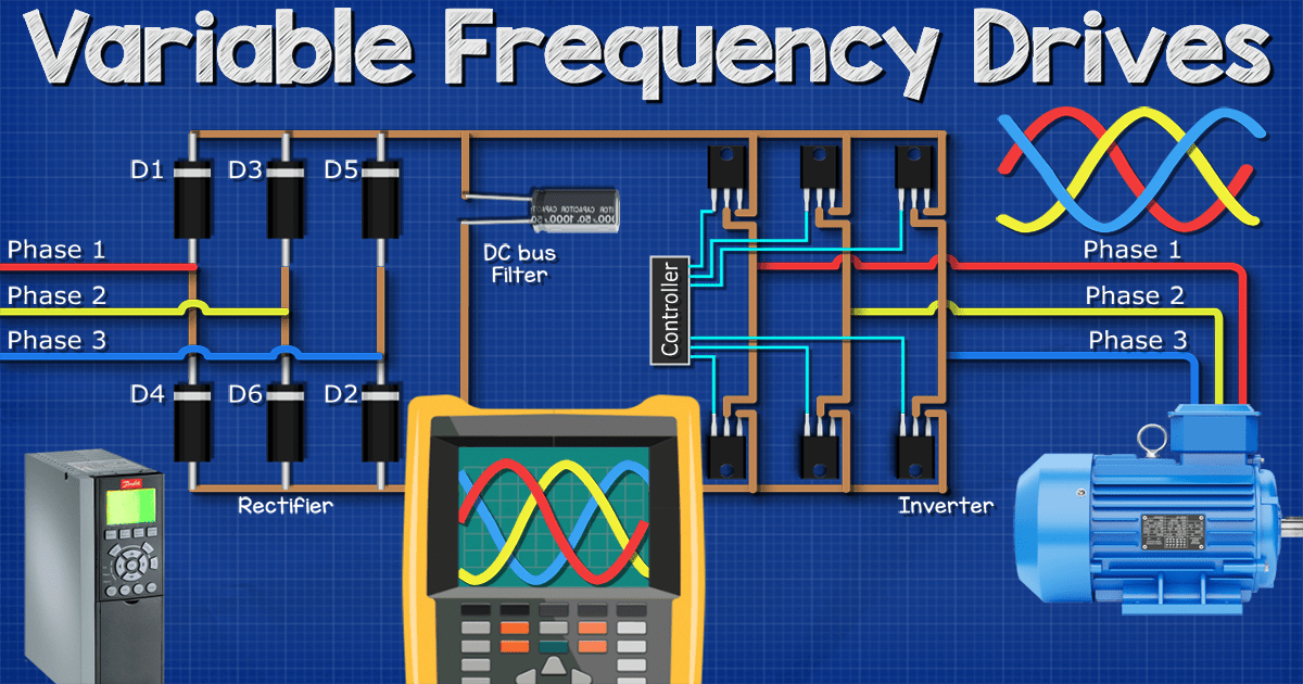
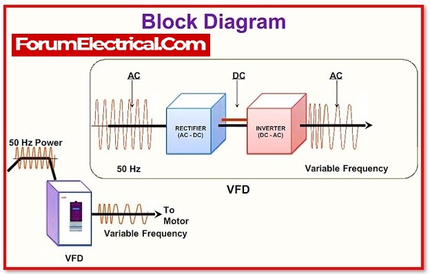
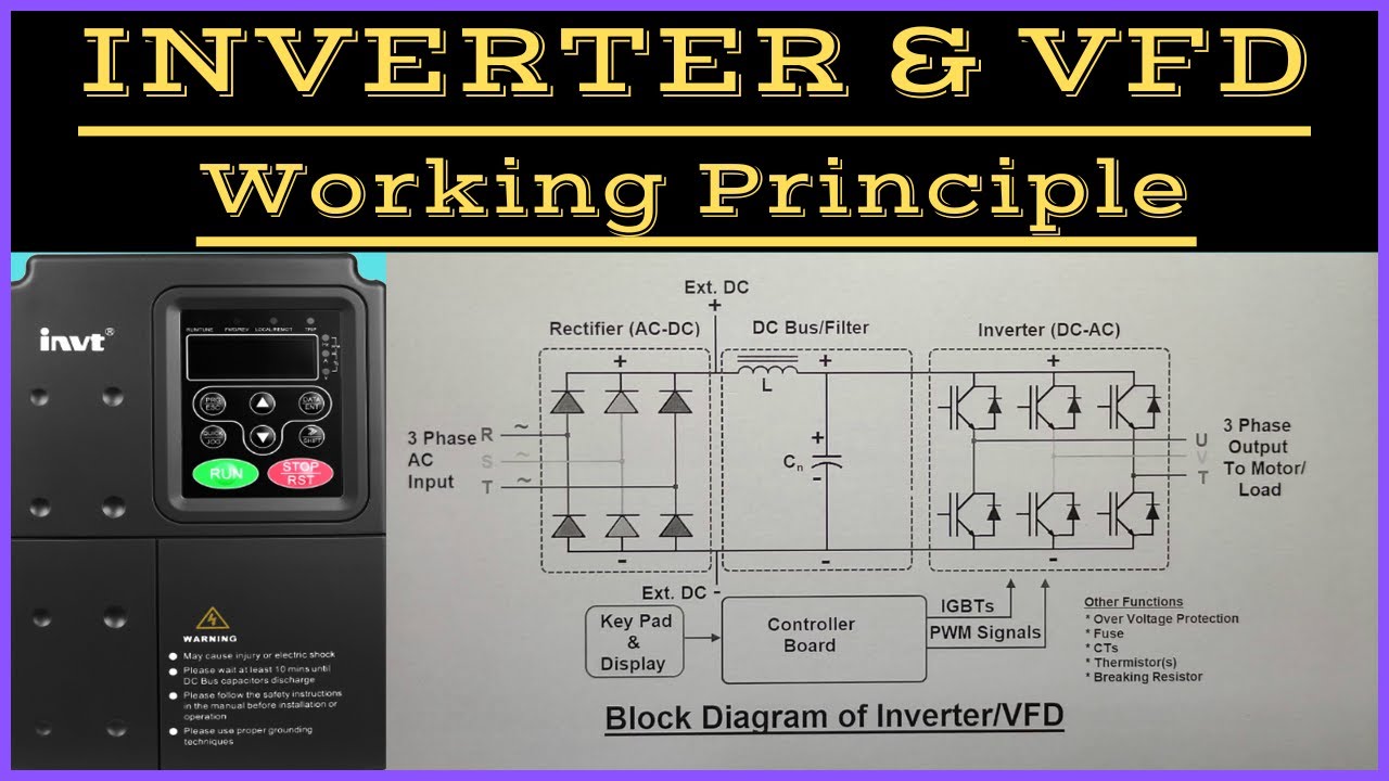
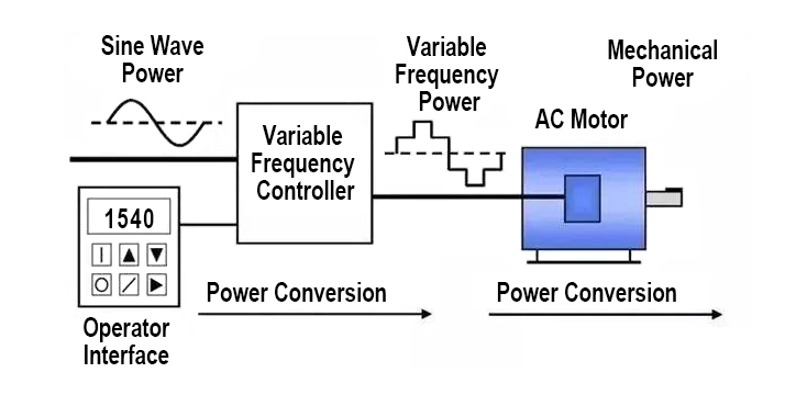
A Variable Frequency Drive (VFD) operates on the fundamental principle of AC-DC-AC power conversion topology. The system receives fixed-frequency AC input (typically 50Hz or 60Hz), converts it to DC via a six-pulse rectifier bridge utilizing diodes or active front-end (AFE) technology, filters the DC through a capacitor bank and inductor network (DC bus), and finally inverts the DC back to variable-frequency AC using insulated gate bipolar transistors (IGBTs) or silicon carbide (SiC) MOSFETs.
The inverter stage employs Pulse Width Modulation (PWM) to simulate a sinusoidal output by rapidly switching the DC voltage on and off at carrier frequencies typically ranging from 2kHz to 16kHz. By varying the pulse width while maintaining a constant volts-per-hertz (V/Hz) ratio, the VFD controls motor magnetic flux and torque. The synchronous speed formula Ns = 120 × f / P governs this relationship, where f represents the output frequency and P represents the number of motor poles. For vector control drives, the system decouples flux and torque components through complex algorithms, enabling precise speed control down to 0.01% accuracy independent of load variations.
Technical Cost Drivers and Selection Criteria
Power Rating and Voltage Class: Drive pricing scales non-linearly with kW rating. Low-voltage drives (230V/460V AC input) dominate industrial applications up to 500kW, while medium-voltage drives (2.3kV–13.8kV) command premium pricing due to series-connected IGBT stacks and isolation requirements. Single-phase 220V input drives cost 15–20% more per kW than three-phase equivalents due to higher current handling requirements and derating necessities.
Control Architecture: Scalar V/f control represents the baseline cost option, suitable for pumps and fans. Open-loop vector control adds 10–15% cost but provides 200% starting torque and dynamic response. Closed-loop vector control with encoder feedback increases costs by 25–30% but enables full torque at zero speed and precise positioning. Direct Torque Control (DTC) variants command premium pricing for high-dynamic applications such as cranes and hoists.
Environmental Protection and Thermal Management: IP20 (open chassis) drives offer baseline pricing, while IP54/NEMA 12 enclosures for dusty environments add 20–25%. IP66/NEMA 4X washdown-rated drives for food processing or outdoor installations increase costs by 40–50% due to sealed heat exchangers and conformal-coated PCBs. High-ambient temperature specifications (above 40°C) require derating or enhanced cooling systems, impacting total cost of ownership.
Power Quality Components: Input line reactors (3% impedance) add 8–12% to system cost but mitigate harmonic distortion (THDi) from 65% to 35%. DC link chokes provide similar benefits at lower cost points. Active front-end (AFE) regenerative drives eliminate braking resistors and return energy to the grid, but cost 60–80% more than standard diode bridges.
MPPT Efficiency (Solar Pump Applications): For solar pump inverters, Maximum Power Point Tracking (MPPT) efficiency directly affects system economics. High-efficiency algorithms (>99% tracking efficiency) utilizing perturb-and-observe or incremental conductance methods reduce required PV array size by 15–20%, offsetting higher drive costs through lower solar panel expenditure.
Industrial Sourcing and System Sizing Guidelines
Load Characteristic Analysis: Variable torque applications (centrifugal pumps, fans) follow the affinity laws where power varies with the cube of speed. Size these drives to the motor nameplate rating without oversizing. Constant torque applications (conveyors, compressors) require drives rated for heavy-duty (150% overload for 60 seconds) rather than normal duty (110% for 60 seconds) to prevent nuisance tripping during startup.
Cable Length Considerations: For cable runs exceeding 50 meters between drive and motor, specify dv/dt filters to prevent voltage reflection and insulation stress. At distances beyond 100 meters, sine wave filters or load reactors become mandatory to protect motor bearings from eddy currents and premature failure.
Altitude and Temperature Derating: Standard VFDs operate at full rating up to 1000m altitude and 40°C ambient. Above these thresholds, derate by 1% per 100m or 1.5% per °C. High-altitude applications (>2000m) require specialized drives with reinforced insulation or external cooling systems.
Braking Requirements: High-inertia loads requiring rapid deceleration necessitate dynamic braking resistors sized to dissipate regenerative energy. Calculate braking duty cycle based on stopping frequency; continuous regenerative applications warrant active front-end drives rather than resistor braking to avoid energy waste and resistor degradation.
Bypass Configuration: Critical applications should include three-contactor bypass arrangements (drive isolation, bypass, and motor protection) to ensure operation during drive maintenance or failure, adding approximately 30% to panel costs but eliminating single points of failure.
Why Source Inverters and VFDs from China?
Related Technical Insight
China has evolved from component assembly to high-value R&D leadership in power electronics. Chinese manufacturers now dominate global IGBT module packaging, magnetic component optimization, and thermal management innovation. The vertical integration of semiconductor foundries, PCB fabrication, and precision machining within regional industrial clusters enables 20–30% cost optimization compared to Western manufacturing while maintaining IEC 61800-5-1 and UL 508C compliance.
Advanced Chinese facilities now utilize automated optical inspection (AOI), automated guided vehicle (AGV) logistics, and Industry 4.0 traceability systems. This manufacturing sophistication, combined with aggressive R&D investment in wide-bandgap semiconductors (SiC and GaN), positions Chinese suppliers as technology leaders rather than commodity producers. For OEMs and system integrators, sourcing from China provides access to cutting-edge vector control algorithms, IoT-enabled predictive maintenance features, and rapid customization cycles unavailable from legacy Western brands.
Boray Inverter: Your Strategic OEM/ODM Partner
Boray Inverter stands at the forefront of motor control technology with a workforce composition where 50% are dedicated R&D engineers, ensuring continuous innovation in drive topology and control algorithms. Our engineering team has achieved complete mastery over both Permanent Magnet Synchronous Motor (PMSM) and Induction Motor (IM) vector control, enabling precise field-oriented control (FOC) for high-efficiency applications ranging from solar pumping to industrial automation.
Our manufacturing infrastructure features two modern, fully automated production lines equipped with robotic assembly and automated testing stations. Every unit undergoes 100% full-load testing before delivery, including thermal runaway verification, overload capacity validation, and EMC immunity testing to ensure zero-defect shipment. This rigorous quality protocol eliminates field failures and protects your project reputation.
Whether you require standard VFDs for HVAC systems, solar pump inverters with advanced MPPT algorithms, or customized drives with integrated PLC functionality, Boray provides comprehensive OEM and ODM services with flexible MOQs and rapid prototyping capabilities. Contact Boray today to discuss wholesale pricing structures and custom firmware solutions tailored to your specific application requirements.
Frequently Asked Questions (FAQs)
What is the difference between V/f control and vector control in VFDs?
V/f (volts-per-frequency) control maintains a constant ratio between voltage and frequency to preserve motor flux, providing adequate performance for variable torque loads like pumps and fans. Vector control decouples the motor’s magnetic flux and torque components through complex mathematical models, enabling independent control of each parameter. This provides 200% starting torque, precise speed regulation (±0.01%), and dynamic response to load changes, essential for applications such as cranes, hoists, and machine tools requiring high starting torque or precise positioning.
Can a VFD cause damage to motor bearings, and how is this prevented?
Yes, VFDs can induce shaft currents due to the high dv/dt switching transients from IGBT inverters, leading to electrical discharge machining (EDM) pitting in motor bearings. This occurs when common-mode voltages exceed the dielectric strength of bearing grease. Mitigation strategies include installing insulated bearings (ceramic or coated races), using shaft grounding rings to divert currents, or specifying sinus wave filters for cable runs exceeding 50 meters. For new installations, specify inverter-duty motors with reinforced insulation (NEMA MG1 Part 31) and insulated bearings.
How do I properly size a VFD for constant torque versus variable torque applications?
For variable torque applications (centrifugal pumps, fans), size the drive to match the motor nameplate current exactly, as the load decreases cubically with speed reduction. For constant torque applications (conveyors, positive displacement pumps, compressors), select a drive rated for “heavy duty” (150% overload capacity for 60 seconds) rather than “normal duty” (110% overload). Additionally, verify the drive can provide the required starting torque—typically 150-200% of rated torque—without tripping on overcurrent. Oversizing by one frame size is recommended for high-starting-torque loads or operation above 45°C ambient temperature.
Is an input line reactor necessary for my VFD installation?
Input line reactors (3% impedance) are necessary when the line voltage imbalance exceeds 3%, when the supply transformer kVA rating exceeds 10 times the drive kVA rating, or when multiple drives share a common bus. They reduce harmonic current distortion (THDi) by 40-50%, prevent nuisance tripping from voltage notching, and protect the drive from transient overvoltages caused by power factor correction capacitor switching. While adding 8-12% to initial costs, reactors significantly extend drive lifespan by reducing DC bus capacitor heating and rectifier stress.
Can I use a single-phase input to power a three-phase motor using a VFD?
Yes, specialized single-phase input drives (typically 220V ±15%) can power three-phase motors by utilizing a derating factor of approximately 50% (e.g., a 5.5kW three-phase motor requires a 11kW single-phase input drive). The VFD rectifies the single-phase input and generates three-phase output through the inverter stage. However, this configuration requires larger DC bus capacitors to handle the higher ripple current inherent in single-phase rectification. For applications above 3kW, consider using a phase converter or upgrading to three-phase supply to avoid excessive input current draw and reduced system efficiency.