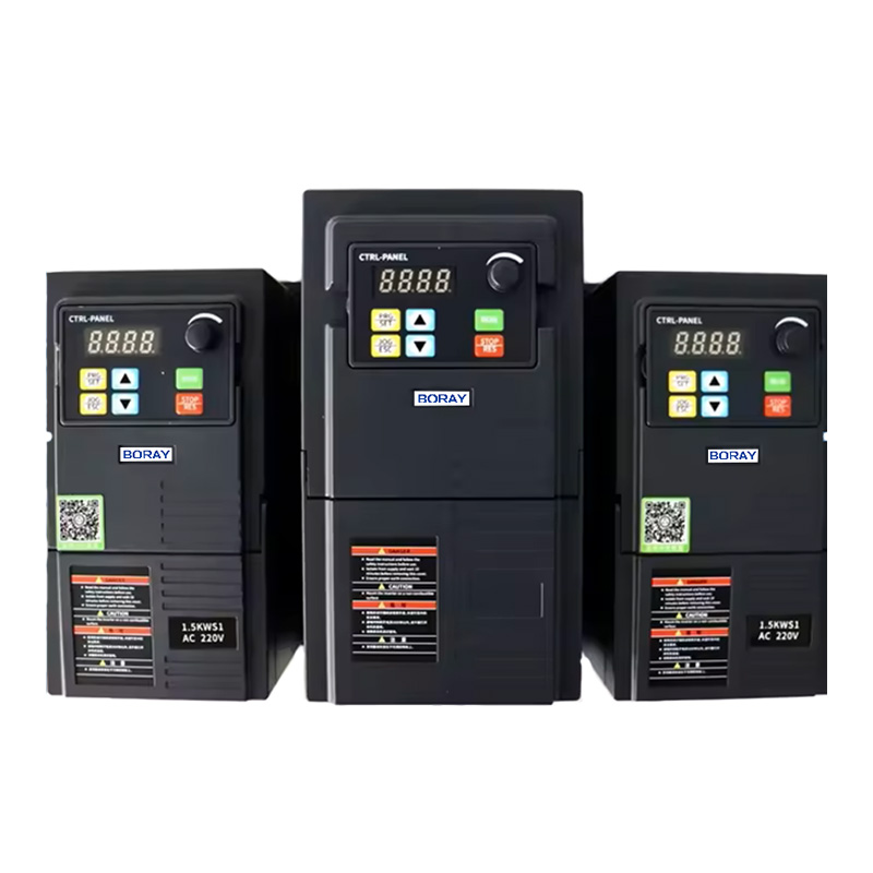
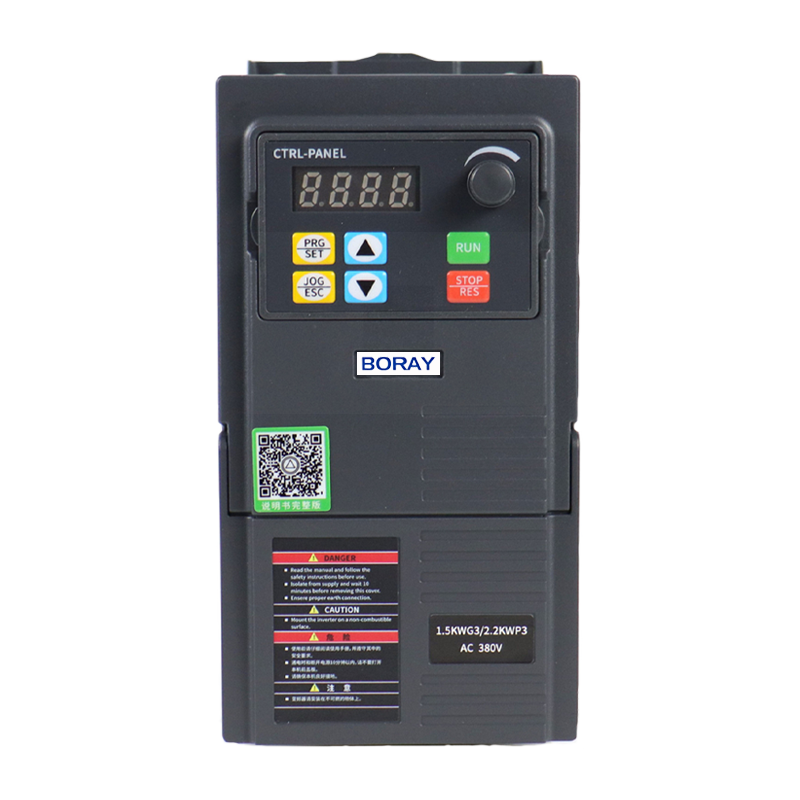
BR100 Variable Frequency Inverter
High-performance frequency conversion technology, Compatible with various asynchronous motors
BR110 Variable Frequency Inverter
High performance control, Wide voltage adaptation and protection, Multifunctional integrated design
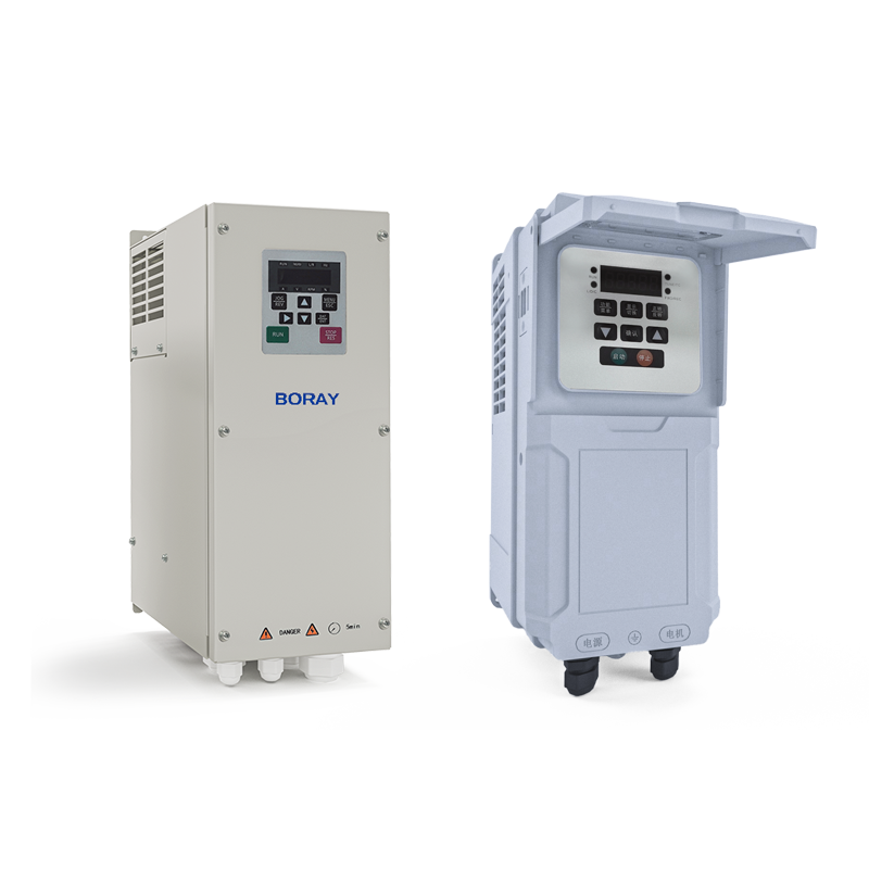
BR500-P Solar Pump Inverter
Green energy product with MPPT technology, Compatible with:AC induction pumps & High-efficiency PMSM pumps
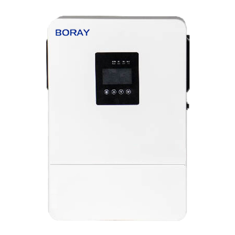
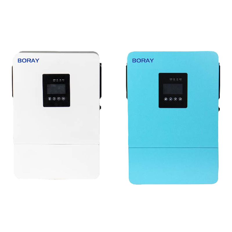
BR2000 Hybrid Solar Inverter
Multifunctional hybrid grid inverter, All-in-one control integration, Single-phase pure sine wave output
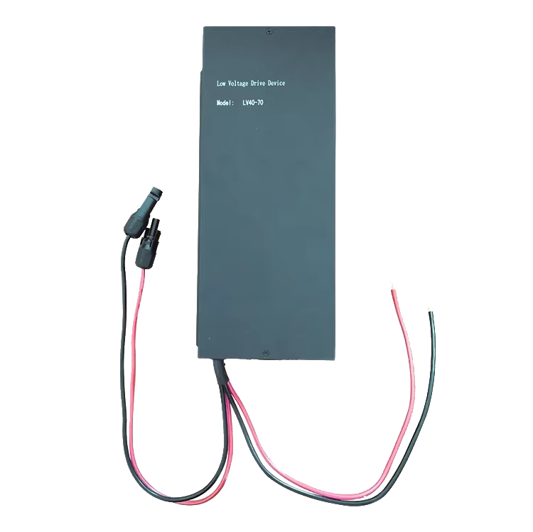
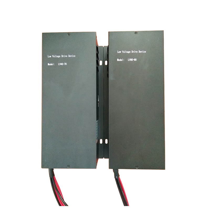
LV40-70 Solar DC Voltage booster
The solar DC voltage booster is a sophisticatedly designed electrical device intended to efficiently convert
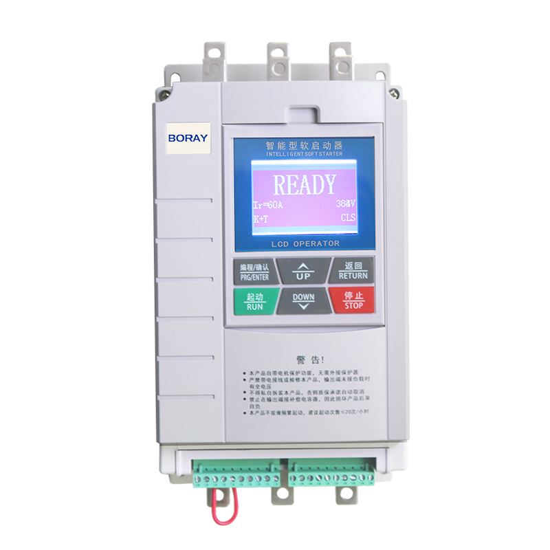
ST100 Bypass Soft Initiator
ST100 bypass intelligent soft starter employs sophisticated digital control technology, utilizing a microcontroller
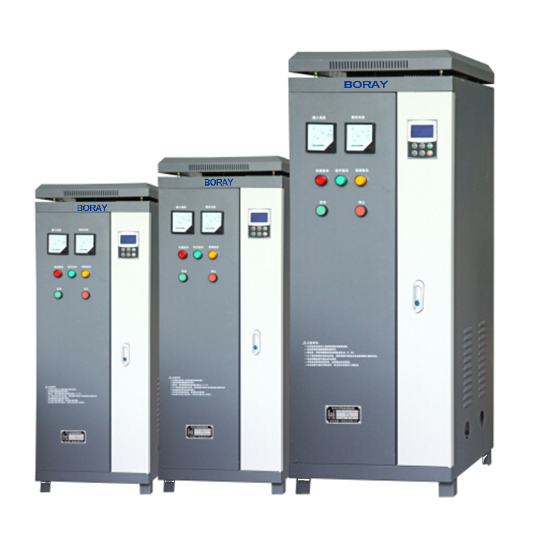
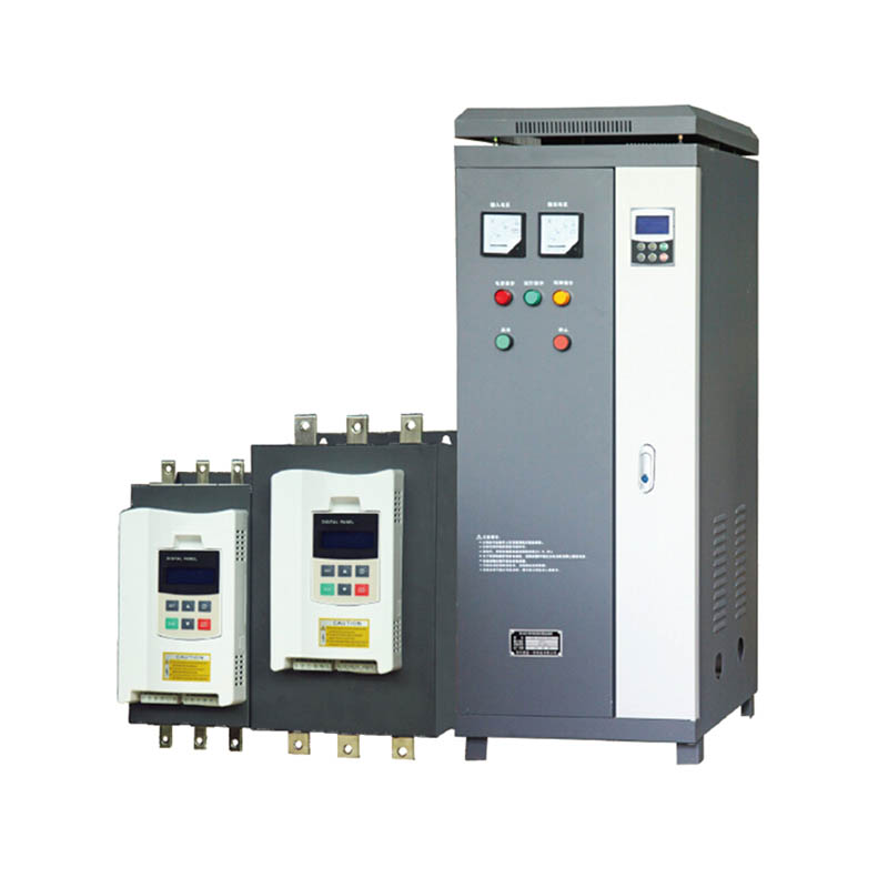
ST300 Online Soft Starter Cabinet
ST300 online soft Starter cabinet is new generation soft starter panel, that with completely function
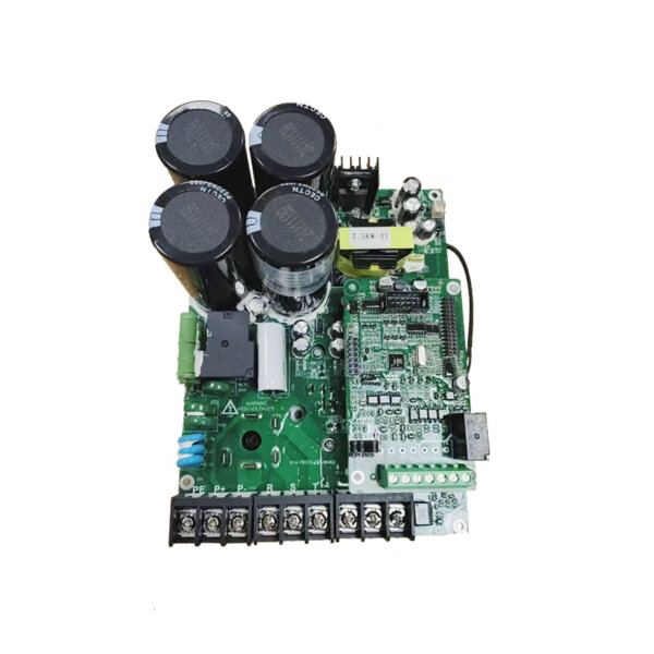
SG Serise PCB Board for Inverter
PCB Board Solar Inverter is a vital com-ponent in solar PV systems, converting DC electricity from solar panels

How Solar Pump Inverters Power Sustainable Farming
As the world turns to renewable energy, solar water pumps have become a game-changer in agriculture, especially in remote and off-grid areas.

The Intelligent Backbone of Renewable Energy Systems
As a key component of renewable energy systems, solar inverters promote smarter and more efficient energy solutions.

MPPT Technology Maximizing Efficiency in Solar Pump Inverters
MPPT technology helps achieve breakthroughs in inverter efficiency and provides key support for agricultural water and energy conservation.

Frequency Inverter use in Energy Power
The global energy industry focuses on efficiency and sustainability, and variable speed drives are crucial to optimizing energy consumption in multiple industries.
